Interferometer systems

a technology of interferometers and interferometers, applied in the direction of interferometers, instruments, manufacturing tools, etc., can solve the problems of significant time elapse before a subsequent disturbance can be detected and located accurately, and the magnitude of the difference in path length cannot be determined by the mach-zehnder interferometer alon

Active Publication Date: 2012-09-06
FIBERSONICS
View PDF7 Cites 24 Cited by
  • Summary
  • Abstract
  • Description
  • Claims
  • Application Information

AI Technical Summary

Benefits of technology

[0018]In some innovative systems, the Mach-Zehnder sensor portion includes the first fiber portion and the second fiber portion, and the first splitter-coupler configured to split incoming light between the first fiber portion and the second fiber portion. A coupler can be configured to join a portion of light in the first fiber portion with a portion of light in the second fiber portion, and a third fiber portion can be configured to receive light from the coupler and to illuminate a second detector (sometimes referred to as a “Mach-Zehnder detector”). Light that passes through the third fiber portion can illuminate the second detector independently of light reflected by the first or second polarization-phase conjugation devices.

Problems solved by technology

Nonetheless, a Mach-Zehnder interferometer alone cannot provide the location of such a disturbance or the magnitude of the difference in path lengths.
Such polarization controllers that provide matched polarization states are costly.
Therefore, a significant amount of time can elapse before a subsequent disturbance can be detected and located accurately.
Since a portion of an incoming beam of light is diverted into each sensitive region (or zone), such a system has practical limitations on the number of zones that are possible when using a given light source.
As a result of being limited to a particular number of zones, there is also a practical limitation on the length of a perimeter that can be monitored with such a system.
However, such a zone can span a relatively large distance, which might not provide a desired spatial resolution for many security applications.

Method used


Image

  • Interferometer systems
  • Interferometer systems
  • Interferometer systems

Examples


Embodiment Construction

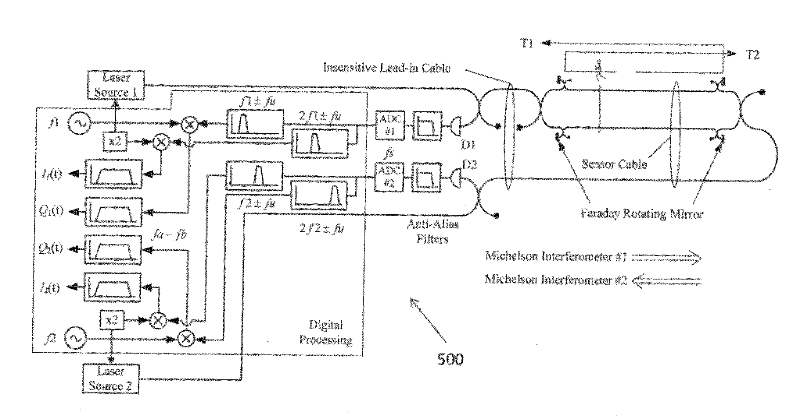
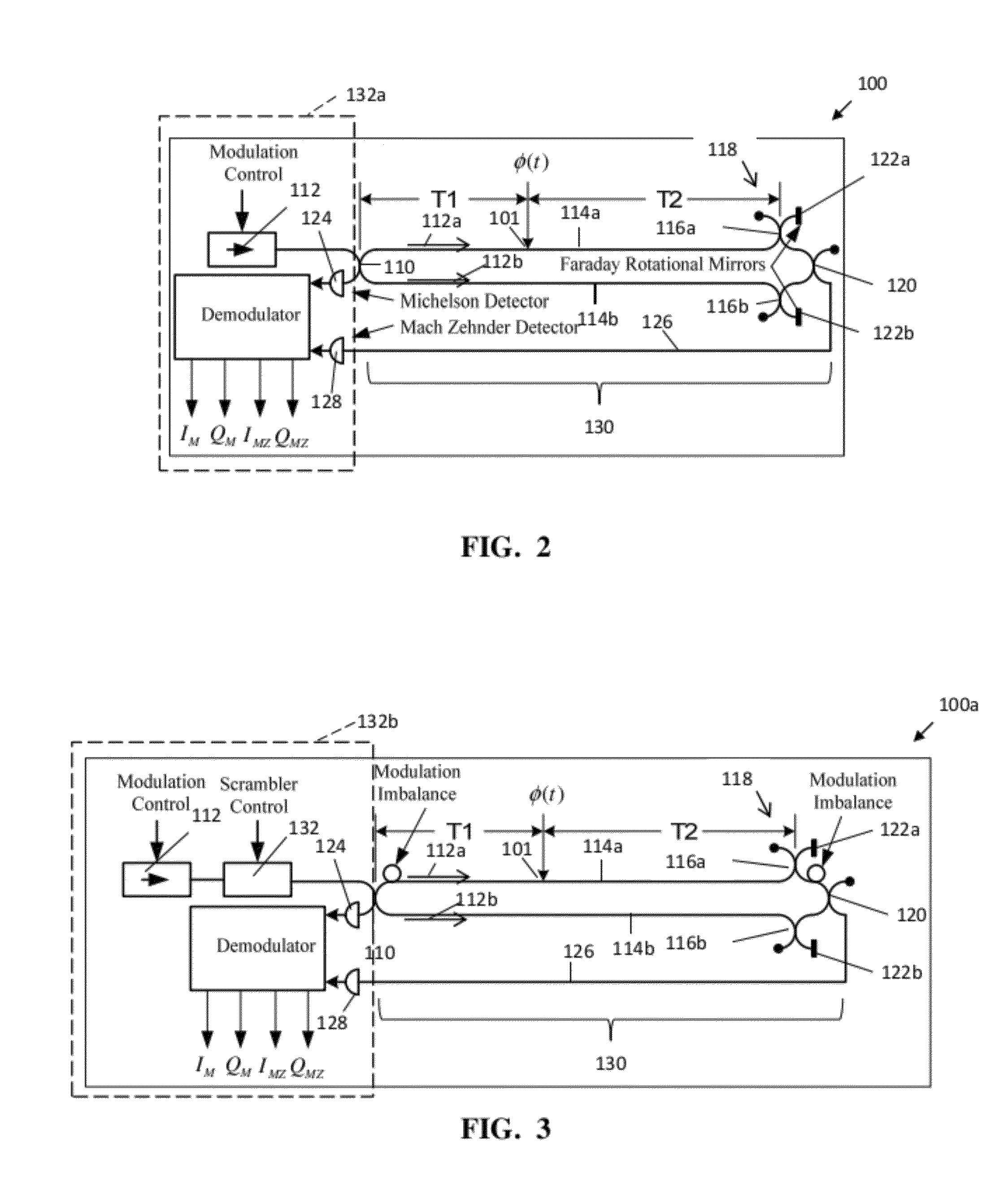
[0039]Various principles related to interferometer systems are described herein by way of reference to exemplary systems. One or more of the disclosed principles can be incorporated in various system configurations to achieve one or more interferometer system characteristics. Systems relating to perimeter security applications are merely examples of innovative interferometer systems and are described herein to illustrate aspects of the various principles disclosed herein. Some embodiments of disclosed innovations may be equally applicable to use in many other applications, such as, for example, detecting a leak in a pipeline, detecting a failure in a structure, detecting a disturbance to a ground surface, detecting a change in operation of a conveyor, etc.

Overview of Innovative Interferometer Systems

[0040]Interferometer systems as disclosed herein can detect a disturbance to a sensor portion by comparing a phase shift between observed first and second optical signals that have trave...


PUM

PropertyMeasurementUnit
lengthaaaaaaaaaa
lengthaaaaaaaaaa
distancesaaaaaaaaaa

Abstract

A fiber-optic sensor can have a Michelson sensor portion and a Mach-Zehnder sensor portion. A first splitter-coupler can be configured to split incoming light between a first fiber portion and a second fiber portion. A first polarization-phase conjugation device can be configured to conjugate a polarization phase of incident light corresponding to the first fiber portion, and a second polarization-phase conjugation device can be configured to conjugate a polarization phase of incident light corresponding to the second fiber portion. Each of the first and second polarization-phase conjugation devices can be configured to reflect light toward a detector and through the respective first and second fiber portions. A coupler can be configured to join light in the first fiber portion with light in the second fiber portion, and a third fiber portion can be configured to receive light from the coupler and to illuminate a second detector.

Description

BACKGROUND[0001]This application is a U.S. National Phase application under 35 U.S.C. §371 of International Application Serial Number PCT / U.S. Pat. No. 11 / 052608 filed Sep. 21, 2011, which also claims the benefit of U.S. Provisional Patent Application Ser. No. 61 / 393,298 and U.S. Provisional Patent Application Ser. No. 61 / 393,321, both filed Oct. 14, 2010, the contents of which are hereby incorporated by reference as if recited in full herein for all purposes.[0002]The innovations disclosed herein pertain to interferometer systems, and more particularly, but not exclusively, to fiber-optic interferometer systems, such as, for example, systems used in security, surveillance or monitoring applications. Some disclosed interferometer systems relate to detecting and locating disturbances (e.g., a disturbance to a secure perimeter, such as a “cut” on a fence, a leak from a pipeline, a change in structural integrity of a building, a disturbance to a communication line, a change in operatio...

Claims


Application Information

Patent Timeline
Patent Type & Authority Applications(United States)
IPC IPC(8): G01B9/02B23P17/04
CPCG01B9/02012G01B9/02079G01B9/02027G01B2290/70G01B9/02G02B6/255Y10T29/49826G01B9/02041G01B9/02049G01N21/8806G01N2201/0612G01N2201/088G02B6/36G01D5/35306G01D5/35325G01D5/35329G08B13/124G08B13/186
Inventor TAPANES, EDWARD
Owner FIBERSONICS
Why Eureka
Try Eureka