Exhaust Gas Denitrifying System having Noise-Reduction Structure

Active Publication Date: 2012-09-06
PANASIA
View PDF5 Cites 18 Cited by
  • Summary
  • Abstract
  • Description
  • Claims
  • Application Information

AI Technical Summary

Benefits of technology

[0026]Further, each of the flow control plates may be provided with a plurality of center holes through which a laminar flow advances in a straight line, whereby the lam

Problems solved by technology

Nitrogen oxides are known to cause acid rain and respiratory disease.
Further, when noises generated by the operation of engines and by the flow of exhaust gas are directly discharged to the external environment together with the exhaust gas, they destroy the external environment and become a target for public gr

Method used


Image

  • Exhaust Gas Denitrifying System having Noise-Reduction Structure
  • Exhaust Gas Denitrifying System having Noise-Reduction Structure
  • Exhaust Gas Denitrifying System having Noise-Reduction Structure

Examples


Embodiment Construction

[0041]Hereinafter, preferred embodiments of the present invention will be described in detail with reference to the attached drawings.

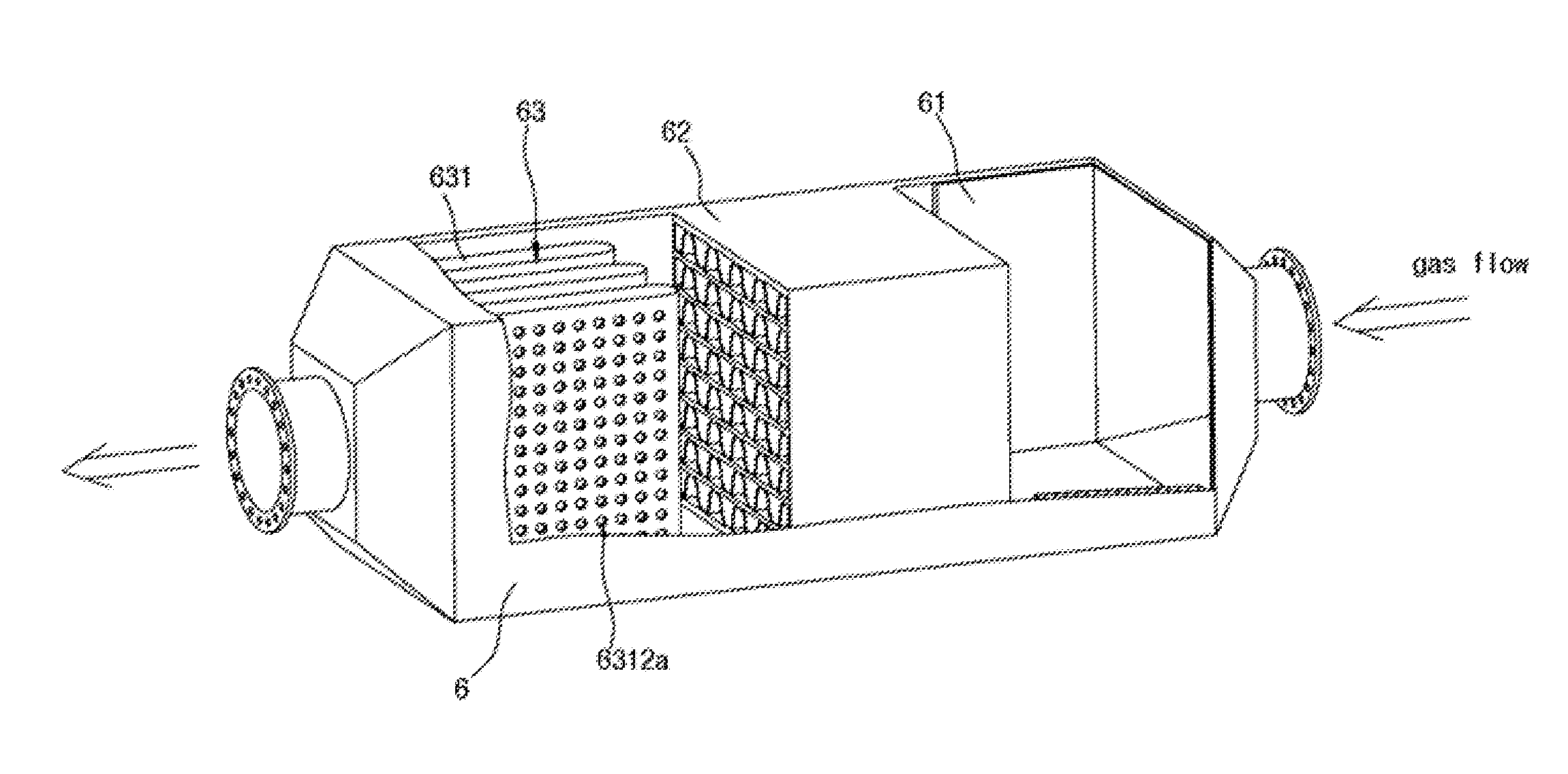
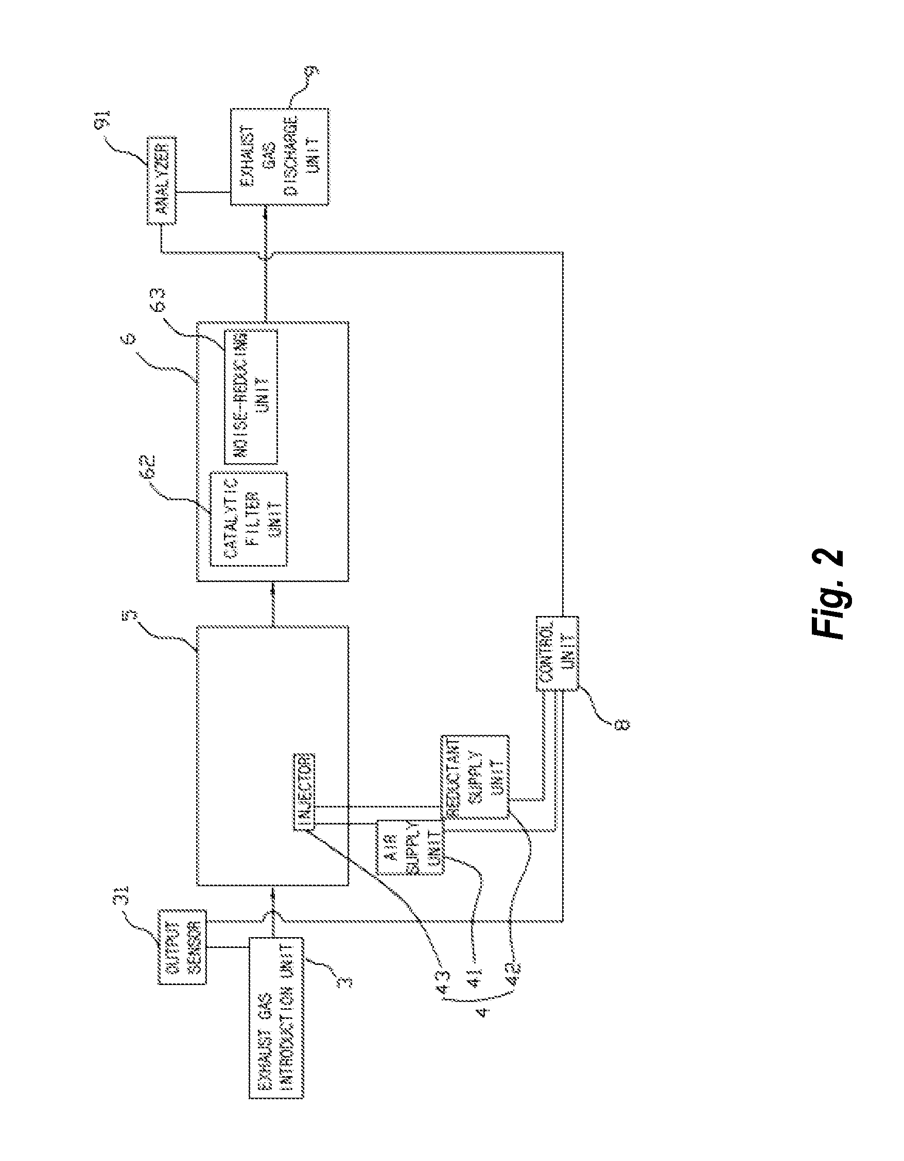
[0042]FIG. 2 is a block diagram of an exhaust gas denitrifying system having a noise-reduction structure according to an embodiment of the present invention, FIG. 3 is a schematic view explaining a reductant injecting unit and a mixing chamber used in the exhaust gas denitrifying system having a noise-reduction structure according to an embodiment of the present invention, FIG. 4 is a perspective view of a reactor used in the exhaust gas denitrifying system having a noise-reduction structure according to an embodiment of the present invention, FIG. 5 is a partially-cut perspective view of the reactor used in the exhaust gas denitrifying system having a noise-reduction structure according to an embodiment of the present invention, FIGS. 6A and 6B are a perspective views of catalytic filter units used in the exhaust gas denitrifying system having a nois...


PUM

PropertyMeasurementUnit
Thicknessaaaaaaaaaa
Pressureaaaaaaaaaa
Flow rateaaaaaaaaaa

Abstract

An exhaust gas denitrifying system having a noise-reduction structure includes a reactor in which a chemical reaction that converts nitrogen oxides included in exhaust gas into nitrogen by denitrifying the nitrogen oxides using a catalyst takes place. The reactor includes a catalytic filter unit coated with a catalyst and provided with a plurality of through-holes through which exhaust gas passes; and a noise-reducing unit for removing noise from the exhaust gas denitrified by the catalytic filter unit. The reactor denitrifies the nitrogen oxides, and simultaneously reduces the noise, thus reducing the size of the exhaust gas denitrifying system.

Description

CROSS-REFERENCE TO RELATED APPLICATIONS[0001]This application claims priority to Korean Application No. 10-2011-0018350, filed on Mar. 2, 2011, which is incorporated herein by reference.BACKGROUND OF THE INVENTION[0002]1. Technical Field[0003]The present invention relates to an exhaust gas denitrifying system having a noise-reduction structure, and, more particularly, to an exhaust gas denitrifying system having a noise-reduction structure, including a reactor in which a chemical reaction of converting nitrogen oxides included in exhaust gas into nitrogen by nitrifying the nitrogen oxides using a catalyst takes place.[0004]2. Description of the Related Art[0005]The exhaust gas discharged from engines for thermoelectric power plants, ships and the like that use fossil fuels as energy sources includes a large amount of nitrogen oxides (NOx). Nitrogen oxides are known to cause acid rain and respiratory disease. Therefore, various technologies for removing nitrogen oxides from exhaust g...

Claims


Application Information

Patent Timeline
IPC IPC(8): B01D53/56
CPCF01N3/30F01N13/0097F01N2330/325B01D53/8631B01D53/8696F01N3/2066F01N3/2828F01N3/2885F01N3/2892F01N1/10B01D2251/2067F01N2230/04F01N2330/06F01N2330/32F01N2570/14F01N2610/02Y02T10/24F01N2240/20Y02A50/20Y02T10/12B01D53/86B01D53/54F01N1/00F01N3/022
Inventor LEE, SOO-TAESONG, OK-RYEOLLEE, CHANG-WONKANG, HA-GEUN
Owner PANASIA
Why Eureka
Try Eureka