
Flat back plate

a back plate and flat technology, applied in the field of back plates, can solve the problems of uncontrollable mechanical stress in the assembled electrodes of a mems capacitor, and uncontrollable mechanical stress in the assembled back plate of a cmos compatible product, so as to achieve greater flexibility in choosing the respective materials and increase the degree of freedom in design

Active Publication Date: 2012-09-06
TDK CORPARATION
View PDF6 Cites 20 Cited by
  • Summary
  • Abstract
  • Description
  • Claims
  • Application Information

AI Technical Summary

Benefits of technology

[0012]The inventors have found that during manufacturing using conventional CMOS processes compressive mechanical stress in an according back plate is created. This mechanical stress may be due to different temperature dependent elastic components of the respective processed materials. As a result of the mechanical stress in the released structure the back plate bends or buckles in an uncontrollable manner and the distance between two electrodes, e.g. between a membrane and a back plate of a MEMS capacitor, is uncontrollable. As a result, the performance of an according microphone is reduced.
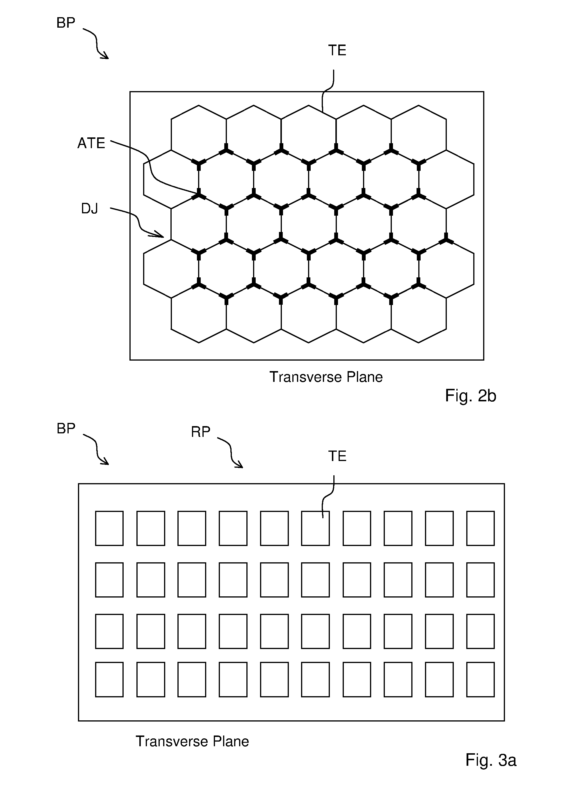
[0038]The tensile stress can be designed by arranging onto the substrate the tensile elements in a semi-connected or connected manner according to a predefined grid pattern joint by aluminum layers located in between the tensile elements. By manipulating the mechanical stress in the back plate unwanted buckling or bending can be reduced or prevented.

Problems solved by technology

However, the application of CMOS production steps often results in an uncontrollable mechanical stress in the assembled electrodes of a MEMS capacitor.
The problem of conventional CMOS compatible produced back plates is a mechanical stress in the assembled back plate.
Using CMOS compatible material the mechanical stress is, in general, compressive and thus the back plate structure bends or buckles in an uncontrollable manner.
Then, the distance between membrane and back plate becomes uncontrollable.
As a result of this, the performance of the microphone is degraded.

Method used


Image

  • Flat back plate
  • Flat back plate
  • Flat back plate

Examples


Embodiment Construction

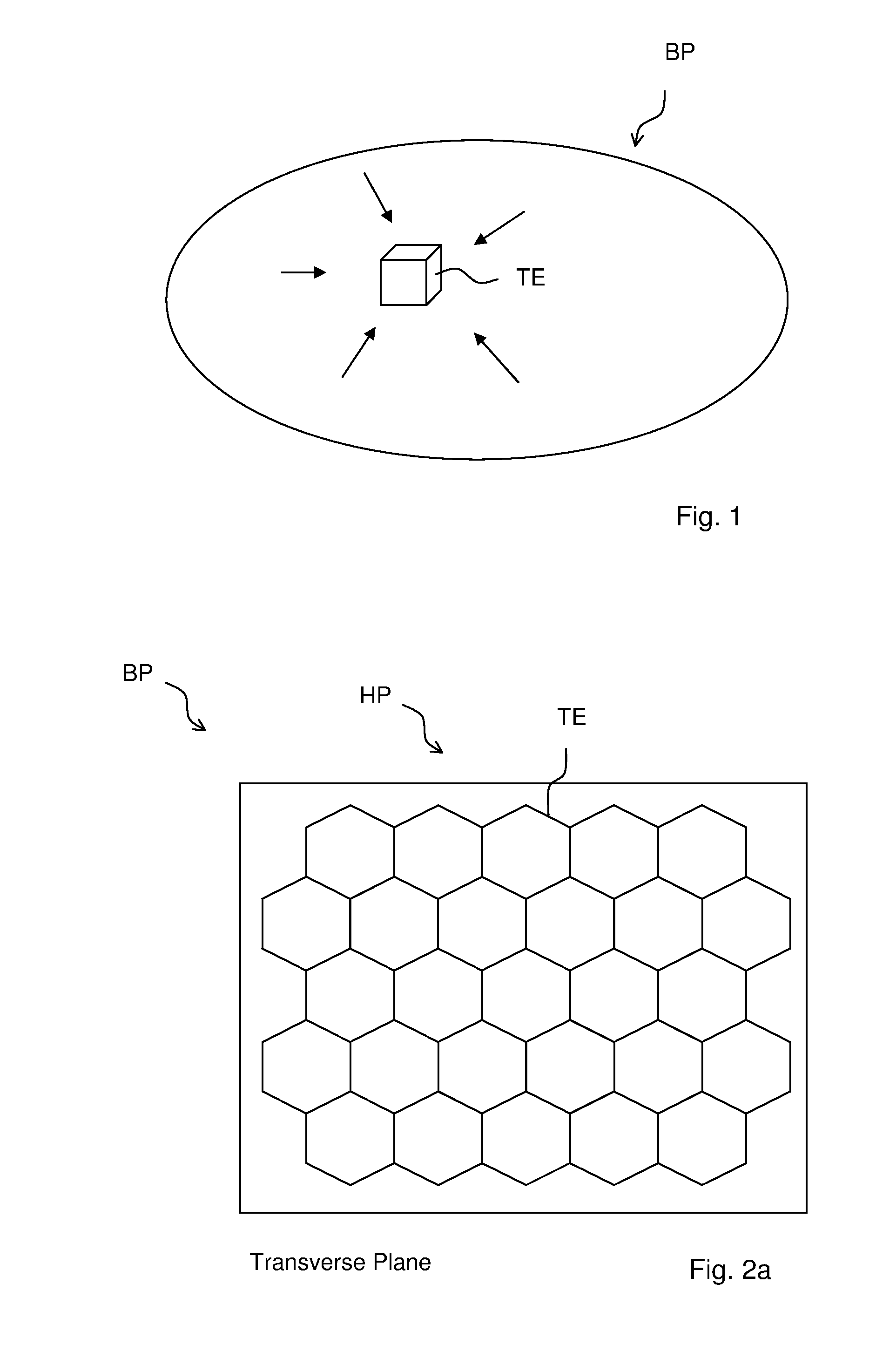
[0049]FIG. 1 shows a perspective view onto a back plate BP comprising a tensile element TE. The tensile element TE exerts a tensile stress. The tensile stress—as indicated by arrows—points at the tensile element TE of the back plate BP within a vicinity of the tensile element TE. Thus, the tensile element TE pulls the adjoining material of the back plate BP and, thus, the total back plate is pulled into a flat shape. This is in contrast to back plates with compressive stress that tends to buckle.

[0050]A flat back plate BP results in a controllable distance between the back plate BP and the compliant membrane of a MEMS microphone. As a result, the performance of a respective MEMS microphone is improved.

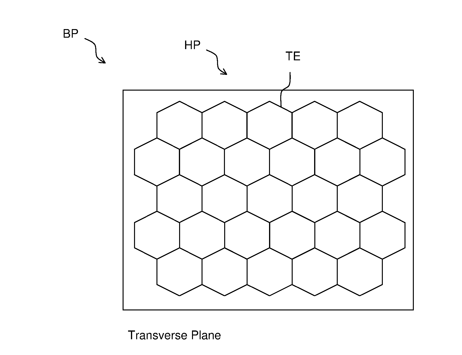
[0051]FIG. 2a shows a transverse plane (top view) of a section of a back plate BP. The back plate BP comprises rod shaped tensile elements TE. The tensile elements TE are arranged in a hexagonal pattern HP. Such a pattern is advantageous because the density of the tensile stress is dis...


PUM

PropertyMeasurementUnit
Lengthaaaaaaaaaa
Lengthaaaaaaaaaa
Lengthaaaaaaaaaa

Abstract

The present invention refers to a flat back plate, e.g. for MEMS capacitors e.g. for MEMS microphones. For that the back plate comprises a tensile element that exerts a horizontal tensile stress on its environment.

Description

FIELD OF THE INVENTION[0001]The present invention refers to back plates, e.g., plates that are used as electrodes of capacitors.BACKGROUND OF THE INVENTION[0002]In general, capacitors comprise two electrodes and a dielectric material between the electrodes. The dielectric material may be an insulator, ceramic or a gas. Capacitors may be used in MEMS devices such as MEMS microphones (MEMS=micro electro mechanical system), MEMS sensors or MEMS switches.[0003]The capacitance of a capacitor having flat electrodes depends on the area of the electrodes, the dielectric material and the distance in between. It is often preferred that one or both electrodes are flat, such, that the distance between the electrodes is well controlled. That is, the electrodes should be flat and arranged in parallel.[0004]MEMS capacitors can be assembled by complementary metal-oxide-semiconductor (CMOS) processing methods. WO 2010 / 092399 refers to a MEMS microphone comprising MEMS capacitors and methods for prod...

Claims


Application Information

Patent Timeline
IPC IPC(8): B32B3/10H01L21/00B32B15/00
CPCB32B15/00B32B3/10Y10T428/24802Y10T29/41Y10T428/25H01L21/00B81C1/00666B81B3/0078B81B2201/0257B81C2201/0167H04R19/005Y10T428/249921
Inventor MORTENSEN, DENNISROMBACH, PIRMIN HERMANN OTTO
Owner TDK CORPARATION
Learn More