
Drying of water damaged buildings

a technology for damp or water damaged buildings and drying methods, applied in drying, lighting and heating apparatus, furnace types, etc., can solve the problems of secondary damage, prolonged drying, inefficiency of refrigerant and desiccant technology, etc., and achieve the effect of improving the efficiency of drying methods and less latent hea

Active Publication Date: 2012-09-13
DAVID & BAADER DBK
View PDF25 Cites 11 Cited by
  • Summary
  • Abstract
  • Description
  • Claims
  • Application Information

AI Technical Summary

Benefits of technology

[0012]In a preferred embodiment, the characteristics are a reduction in the rate of increase of temperature over time.
[0016]In this way an operator can set a maximum temperature or humidity in the room, say 40 degrees Celsius, and when obtained—often in the latter stages of the drying process—that maximum can be used to trigger exhausting of the humid air. Thus, the air can be exhausted before the predetermined room temperature characteristics are attained. This prevents the room becoming too hot or too humid.
[0018]Where relatively cold air is drawn into the room being dried it is preferably pre-heated to reduce the risk of condensation.
[0022]Preferably, the heater is also used to pre-heat outside ambient air to reduce the risk of condensation occurring in the room being dried.
[0024]Conveniently, the apparatus also includes means for recording energy used during the drying process so as to maximise the energy efficiency, and a timer for recording data at required intervals, such as hourly.

Problems solved by technology

Refrigerant and desiccant technology has known inefficiency outside the optimum temperature / relative humidity range within the area being dried.
Also, heat drying alone creates a rapid increase in relative humidity within the area being dried resulting in secondary damage from the heat itself or prolonged drying or cessation of the drying efficiency.
Similarly, with the methods involving dehumidification using the refrigeration or desiccant process, or by using direct heating to raise the temperature of the air in the room, unless the moisture level is constantly monitored there is no indication as to when the process has been satisfactorily completed, leading to increased risk of secondary damage, uncertainty and the potential for energy wastage after the initial objective of drying a damp or waterlogged room has been achieved.

Method used


Image

  • Drying of water damaged buildings
  • Drying of water damaged buildings
  • Drying of water damaged buildings

Examples


Embodiment Construction

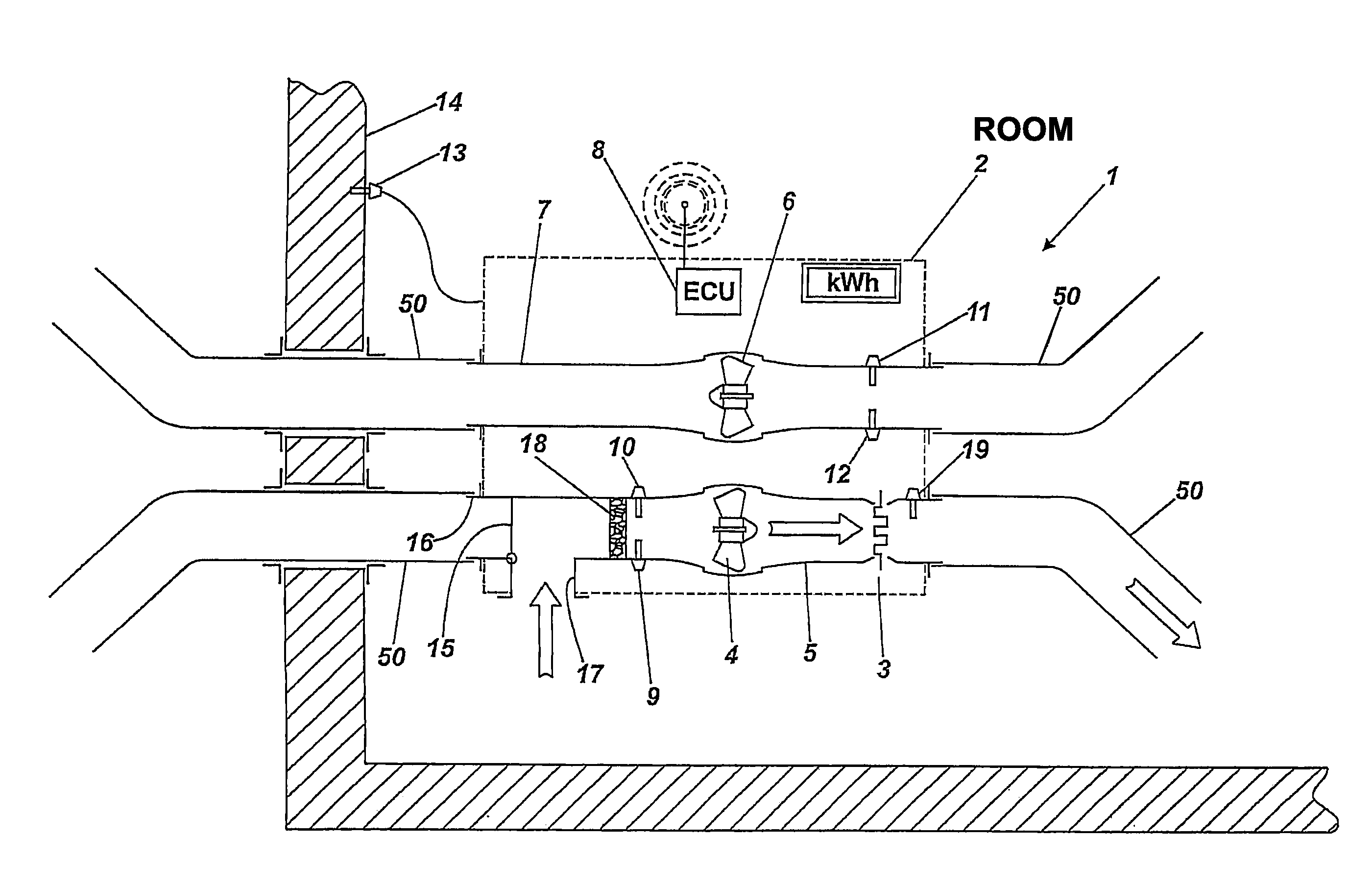
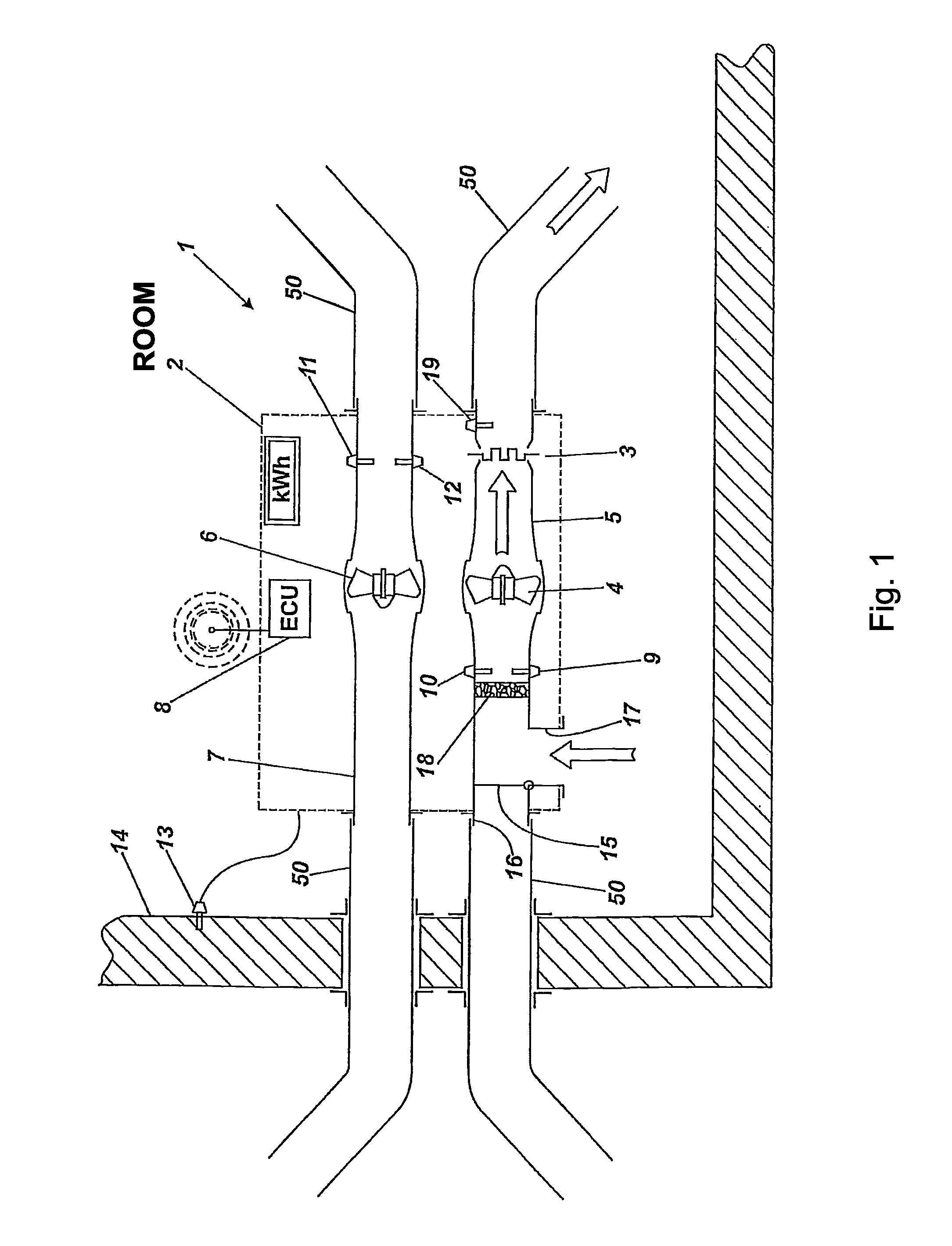
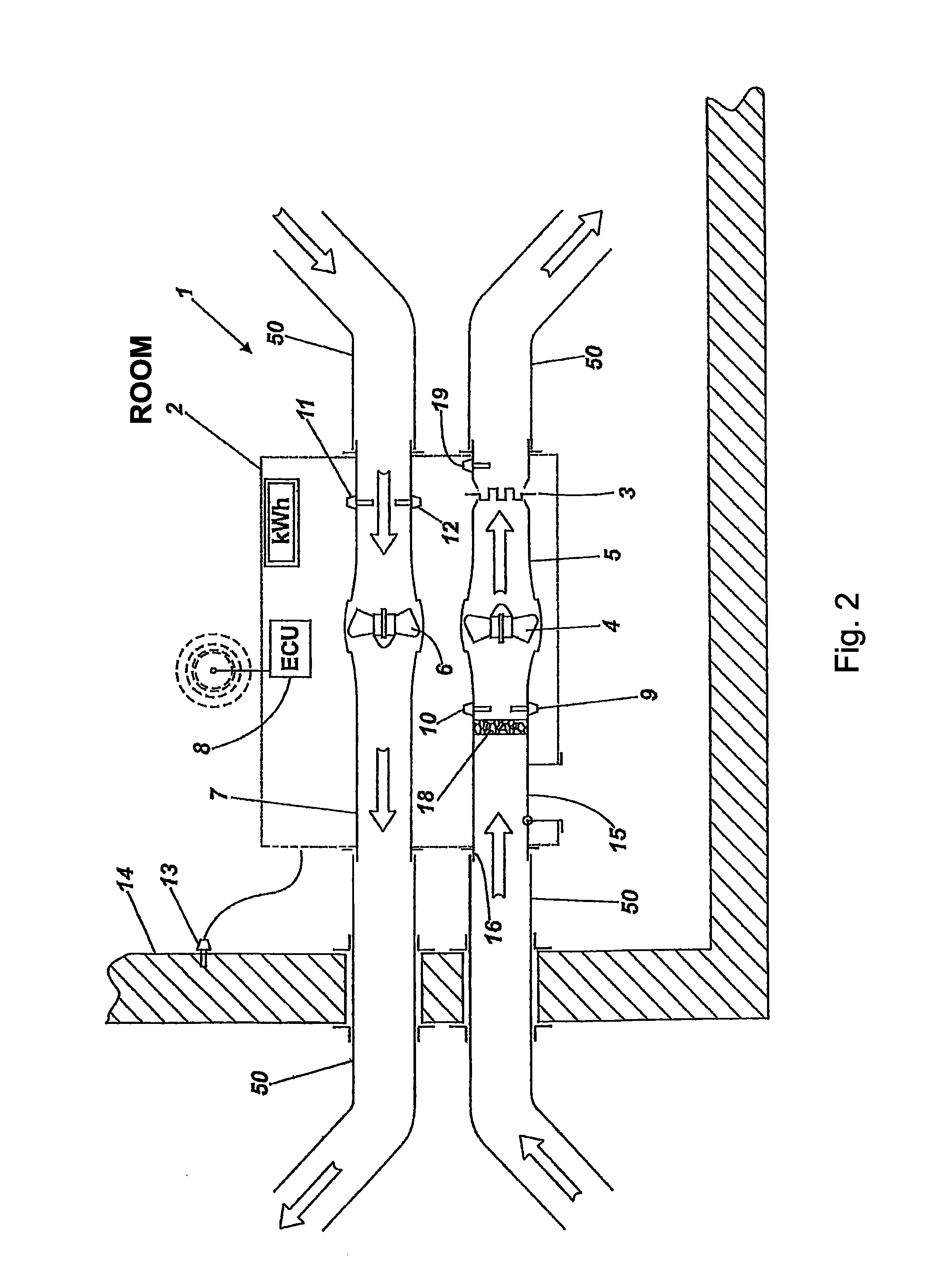
[0034]Turning to FIG. 1 there is shown a schematic view of part of a waterlogged room to be dried in accordance with the method of the invention in which drying apparatus shown generally at 1 includes a heater housing 2 containing a heater element 3 and inlet fan 4 housed within an inlet duct 5 as well as outlet fan 6 and outlet duct 7, collectively by which heated air may be circulated within the room and exhausted from it when required.

[0035]The apparatus 1 also includes an electronic control unit (ECU) 8 which monitors sensed signals from a temperature sensor 9 and a humidity sensor 10 upstream of the air intake fan 4 as well as exhaust temperature sensor 11 and exhaust humidity sensor 12 upstream of the exhaust fan 6. In addition, the ECU 8 also monitors via a wall-mounted humidity or conductivity sensor 13 the amount of water in the wall 14 of the room being dried. Sensor 13 or further sensors may be mounted anywhere in the room, for example on the floor or on the ceiling. Cont...


PUM


Abstract

A drying apparatus for temporary location within a damp or waterlogged room is disclosed. The apparatus includes sensors to sense the level of temperature and humidity within the room, a heater to provide heat for the room, an air circulation fan for selectively circulating heated air within the room or selectively exhausting warm and humid air from the room and for allowing outside ambient air into the room. The apparatus being adapted to cyclically continue until the sensed humidity reaches a required level, the apparatus thereafter indicating, directly or indirectly, the completion of the drying process. A method of drying a room using such apparatus is also disclosed which employs a technique whereby the rate of change of the temperature increase is used to determine when humid air should be exhausted from the room. A time limit can also be use to determine when said exhausting takes place.

Description

CROSS-REFERENCE TO RELATED APPLICATIONS[0001]This patent claims priority from United Kingdom Patent Application No. GB1103899.9, filed Mar. 8, 2011, and United Kingdom Patent Application No. GB1203155.5, filed Feb. 23, 2012, which applications are incorporated herein by reference in their entireties.FIELD OF THE INVENTION[0002]This invention relates to methods and apparatus for drying damp or water damaged buildings, such as those that have been damaged by floods, particularly, but not exclusively, portable apparatus for temporary location in a room of previously flooded building, to dry that room.BACKGROUND OF THE INVENTION[0003]With apparent increases in global warming causing increased flooding there has been correspondingly increased interest in methods of ameliorating the effects of flooding, more particularly in the knowledge that with flood prevention being extremely difficult the focus of attention is increasingly directed towards limiting the damage caused by flooding and d...

Claims


Application Information

Patent Timeline
IPC IPC(8): F26B3/02F26B19/00
CPCE04B1/7015F26B9/02F26B3/04E04B1/7069F24F2110/20F24F11/30F24F2110/10F24F3/14F24F11/0001F26B21/001F26B21/08F26B21/10
Inventor HOPKIN, IAN DAVIDJAYNE, JONATHAN ROBERT
Owner DAVID & BAADER DBK
Learn More