
Modular Green Roof System

a green roof and module technology, applied in the field of plant husbandry and to receptacles for growing media, can solve the problems of unsightly barren lines, inability to overcome the disadvantages mentioned, and unsatisfactory conditions, and achieve the effect of convenient root spread and moisture equalization, effective method of supply and distribution, and continuous and natural appearan

Inactive Publication Date: 2012-09-13
JASLOW LEE
View PDF17 Cites 21 Cited by
  • Summary
  • Abstract
  • Description
  • Claims
  • Application Information

AI Technical Summary

Benefits of technology

[0016]There has been summarized above, rather broadly, the prior art that is related to the present invention in order that the context of the present invention may be better understood and appreciated. In this regard, it is instructive to briefly consider the objects and advantages of the present invention.
[0017]It is an object of the present invention to provide a completely new modular green roof system that combines some of the best features of continuous and modular systems.
[0018]It is also an object of the present invention to provide an improved modular green roof system that facilitates root spread and moisture equalization between trays, giving the roofs on which th

Problems solved by technology

The challenge for modular systems has been to achieve the aesthetics, performance, and economics of continuous systems without losing the key modular system features of simplicity and portability.
A disadvantage of these solid sidewalls is that they prevent the exchange of plant roots and moisture between adjacent trays; meanwhile, the solid sidewalls tend to promote the roots within a tray encircling the tray's interior—which is an undesirable condition for long-term plant health.
The result is an unsightly grid of barren lines in what would preferably be the sight of continuation vegetation.
Trays having flange-less, non-solid sidewalls have also been used, but they have not been able to overcome the disadvantages mentioned above.
For example, see USPPN 2007 / 0094927 which uses sidewalls having large open areas that are covered by screening / filtering / separation materials or fabrics to retain the contents of the trays in place—however, such fabrics are known to be prone to long-term clogging from fine particles in planting media.
See also USPPN 2009 / 0320364 which uses a two-part sidewall where the top part of the sidewall is either removable after the tray's installation or is biodegradable—however, the remaining part of this sidewall remains solid and therefore still suffers to a degree from the disadvantages previously mentioned for solid sidewall trays, and removal of top part of the trays defeats certain advantages of modular systems relating to roof-leak repair and future portability.
With either approach, water can only move outward from the trays, making it difficult to achieve moisture equalization between adjacent trays which would require both inward and outward water movement.
Additionally, the solid bottoms of trays make it difficult to provide supplemental irrigation to such trays.
Lack of care during installation of today's modular green roof trays can result in gaps between adjacent trays.
Additionally, without sidewall flanges for stiffening, trays tend to bow outward from the internal pressure of planting media, making a tight fit difficult.
Connecting sidewalls with conventional mechanical fasteners in an attempt to eliminate these problems can be difficult and time consuming.
Some systems attempt to eliminate gaps by overlapping or interlocking sidewalls (see USPPN 2009 / 0320364 and USPPN 2007 / 0157514), but these require accurate fitting which is difficult when plants obscure the sidewalls, and overlapping connections make module removal difficult.
Current modular green roof trays are designed for low-slope roofs and do not have sufficient structural strength to resist the compressive loads on slopes.
For these reasons, sloped roof applications require considerable improvisation and custom engineering.
An additional problem encountered in using today's modular green roof trays is their transport, which can be expensive since few provisions are provided in their configurations to assist with stacking them for transport in a manner that will protect their vegetation and media from compression.
Often the modules are delivered to the roof on expensive, custom-made, shelf systems.

Method used


Image

  • Modular Green Roof System
  • Modular Green Roof System
  • Modular Green Roof System

Examples


Embodiment Construction

[0044]Before explaining at least one embodiment of the present invention in detail, it is to be understood that the invention is not limited in its application to the details of construction and to the arrangements of the components set forth in the following description or illustrated in the drawings. The invention is capable of other embodiments and of being practiced and carried out in various ways. Also, it is to be understood that the phraseology and terminology employed herein are for the purpose of description and should not be regarded as limiting.

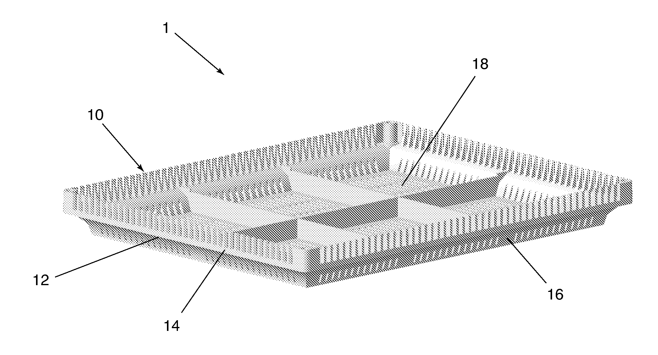
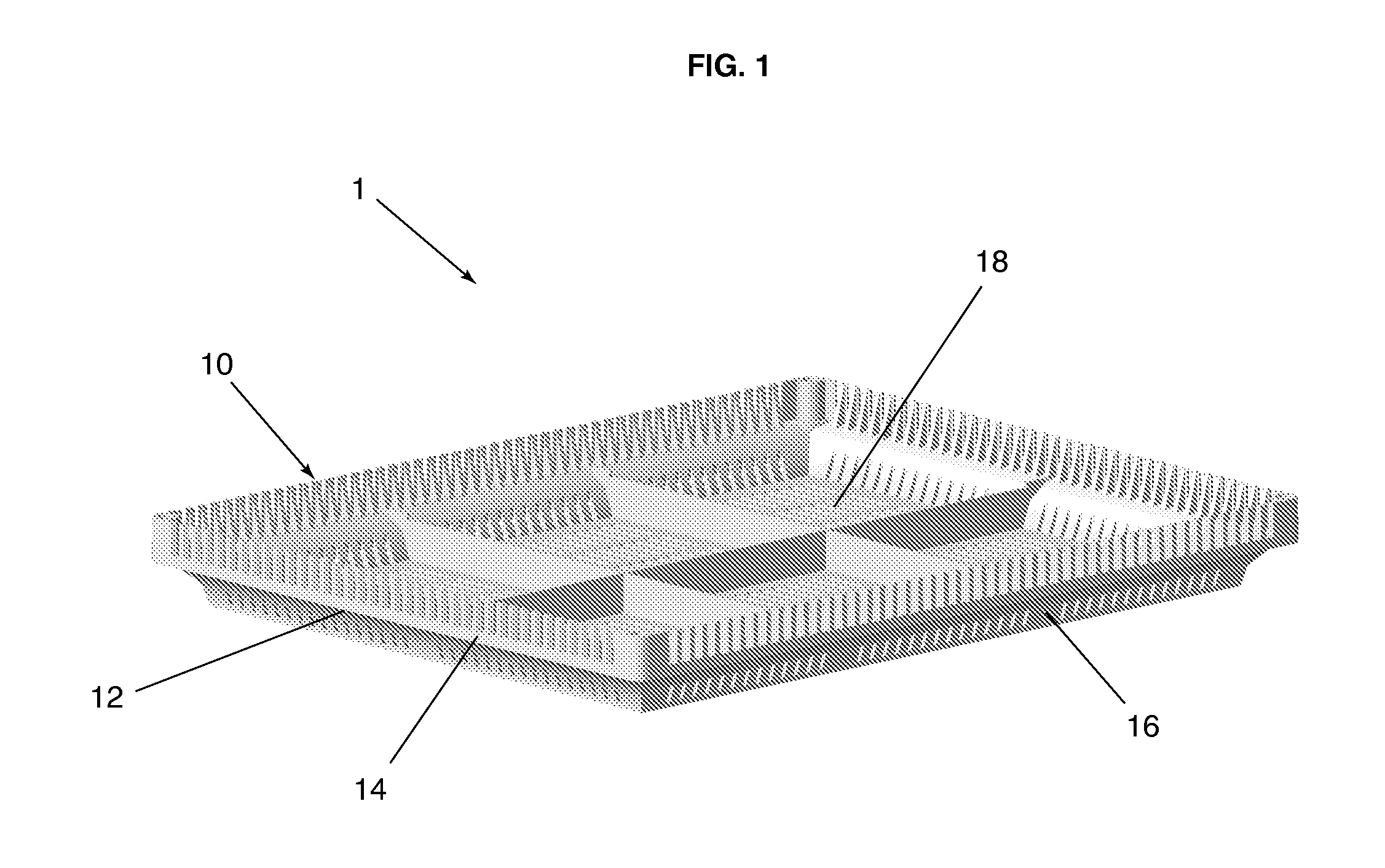
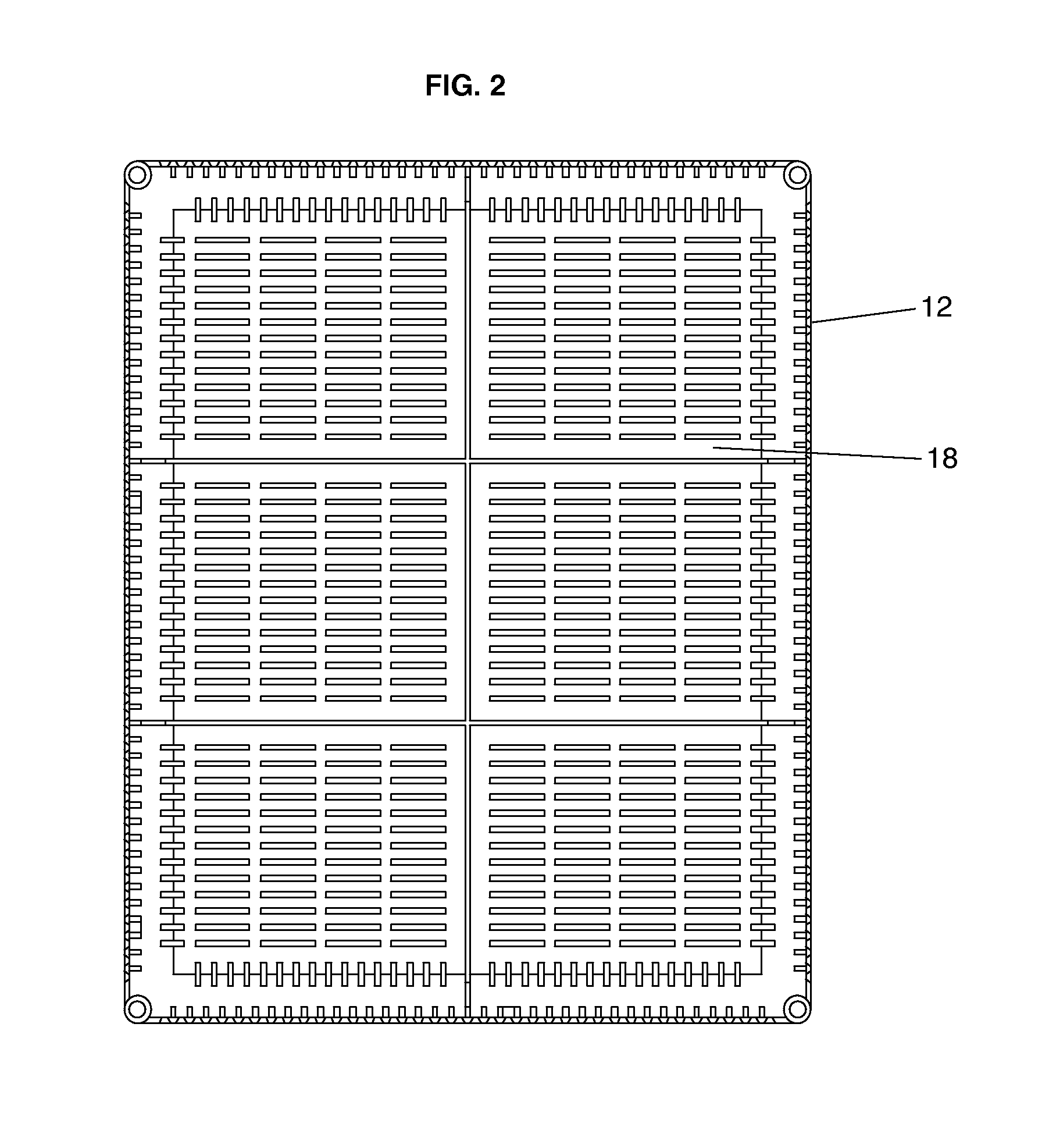
[0045]FIG. 1 shows a perspective view of the preferred embodiment of the present invention 1. This preferred embodiment consists of an injection-molded, plastic, rectangular tray 10 for use in modular green roof applications. The tray has four sidewall surfaces 12 and a bottom surface 18, all surfaces having a plurality of slots or perforations. Each of the sidewall surfaces consists of an upper portion 14 and a lower portion 16. S...


PUM


Abstract

An improved modular green roof system for installation on a roof includes: (a) trays, each having a surface chosen from the group of sidewall, bottom and a combination of such surfaces, and having drainage openings that limit the movement of planting media through the surface while promoting maximum root growth and water and moisture transport through the surface, (b) a water management passage, (c) a structural member that extends across each of the trays and attaches to the opposing bottom sidewall to provide rigidity to each tray, (d) locking members for use with the trays, and wherein each of the trays have a locking opening configured to accommodate one of the locking members, (e) stacking members for use with the trays, and wherein each of the trays have a stacking opening configured to accommodate the insertion of one the stacking members, (f) a slope stabilization device, a portion of which is configured to be accommodated in water management passages, and (g) a water retention medium configured for placement below and in direct contact with the tray's bottom surface.

Description

BACKGROUND OF THE INVENTION[0001]1. Field of the Invention[0002]The present invention relates generally to plant husbandry and to receptacles for growing media. More particularly, the present invention relates to improved, modular, planting systems for roof applications.[0003]2. Description of the Related Art[0004]A “green roof” is a building roof covered with vegetation. “Green roofs” have many attributes that make them preferable to the traditional black, one-dimensional roofs which they often replace, these include: (a) water retention characteristics that dramatically reduce and delay rainwater runoff, (b) heat-absorption characteristics that result in low ambient surface temperatures, largely eliminating summer heat gain to the building below as well as heat radiation to the local environment (known as the urban “heat island” effect), (c) thermal insulation properties that significantly reduce winter heat loss from the building below, and (d) aesthetic and biodiversity characte...

Claims


Application Information

Patent Timeline
IPC IPC(8): A01G9/02
CPCA01G1/007A01G9/033
Inventor JASLOW, LEE
Owner JASLOW LEE
Learn More