Apparatus for forming deposited film

a technology of deposited film and apparatus, which is applied in the direction of sustainable manufacturing/processing, final product manufacturing, vacuum evaporation coating, etc., can solve the problems of deposited film degradation, film quality degradation, and ions and electrons damage to deposited film by charged particles,

Active Publication Date: 2012-09-13
KYOCERA CORP
View PDF2 Cites 14 Cited by
  • Summary
  • Abstract
  • Description
  • Claims
  • Application Information

AI Technical Summary

Benefits of technology

[0017]According to the apparatus for forming deposited film, it is possible to uniformly supply a material gas having a low flow rate from each supply part into a chamber while suppressing a deformation caused by a thermal expansion of an electrode plate. Consequently, it is possible to form, on a substrate, a deposited film which has a uniform film thickness distribution and is excellent.

Problems solved by technology

The plasma CVD method uses a plasma, thereby damaging a deposited film by charged particles, such as ions and electrons.
For this reason, there is a fear that a film quality of a deposited film might be degraded.
However, an excessive decomposition of a material gas (for example, an SiH4 gas) is caused by a heated catalyzer which is heated to a high temperature so that a generation of SiH2, SiH and Si causing a degradation in a film quality progresses.

Method used


Image

  • Apparatus for forming deposited film
  • Apparatus for forming deposited film
  • Apparatus for forming deposited film

Examples


example

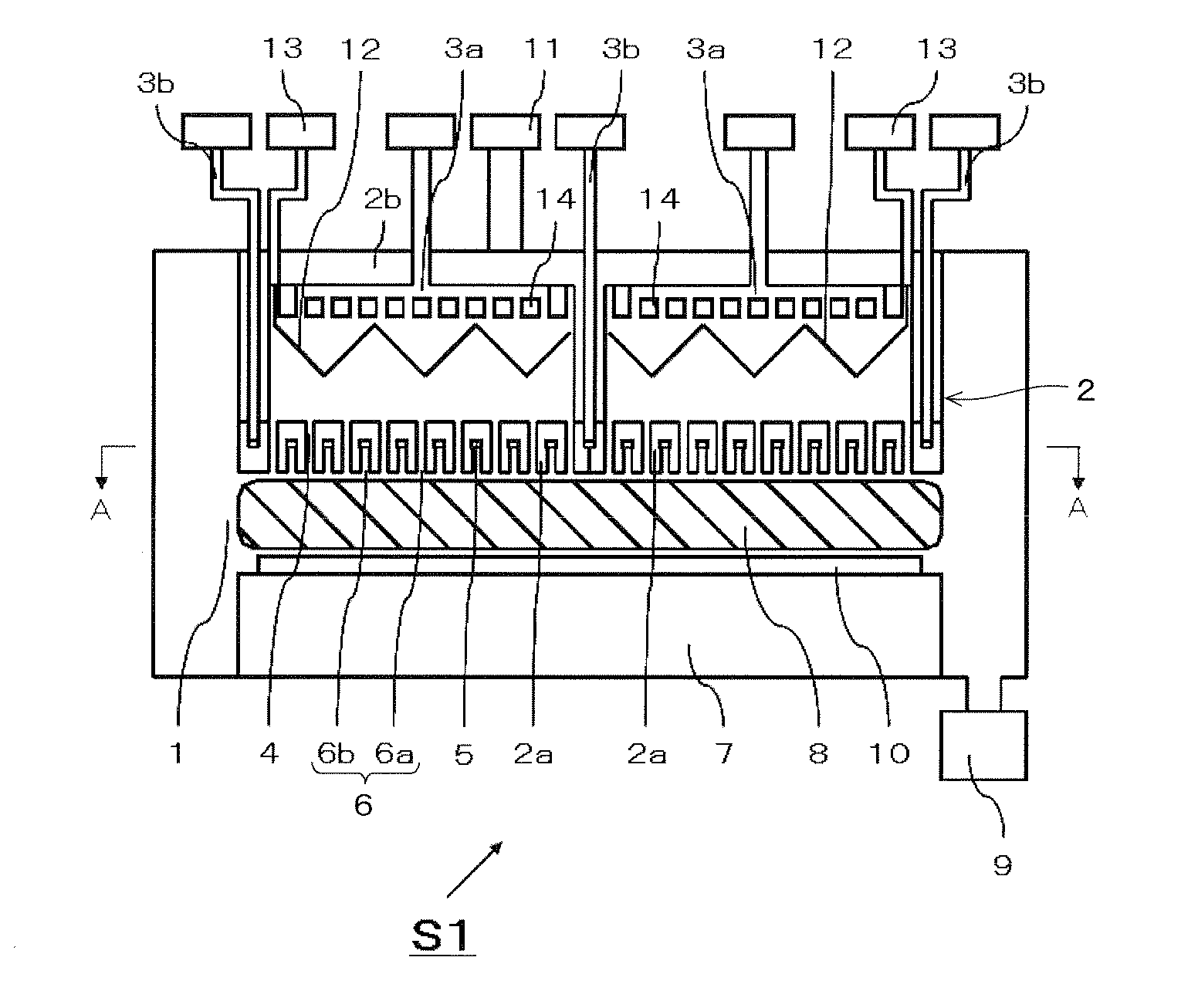
[0107]By supplying an Ar gas (a carrier gas) and an NF3 gas (a cleaning gas) into the chamber from the first supply part and the second supply part using the apparatus for forming deposited film shown in FIG. 1, respectively, the thin film forming apparatus was cleaned.

[0108]In an example 1, a hydrogen gas was supplied from the first supply part and the second supply part into the chamber while the heated catalyzer was heated to 1500° C. after the cleaning step, and a high frequency power was applied to the second electrode to carry out a hydrogen plasma treatment for 20 minutes.

[0109]Moreover, in an example 2, the hydrogen gas was supplied from the first supply part and the second supply part into the chamber while the heated catalyzer was heated to 1500° C. in the same manner as in the example 1, a high frequency power was applied to the second electrode to carry out the hydrogen plasma treatment for 20 minutes, the heating of the heated catalyzer was stopped, and the inner part o...


PUM

PropertyMeasurementUnit
temperatureaaaaaaaaaa

Abstract

First and second electrodes are apart from each other in a chamber. Plates are disposed on a substrate in the second electrode. Each of the plates comprises first and second parts for supplying first and second gas to a space between the first and second electrodes, respectively, a first supply path for first gas connected to the first part, and a second supply path for second gas connected to the second part. The substrate comprises a heater for the first gas, a first introducing path for introducing the first gas to the first supply path, and a second introducing path for introducing the second gas to the second supply path. The second supply path comprises a mainstream part without the second part and branch parts with the second part. A connecting portion of the second introducing path and the mainstream part is positioned in an adjacent portion of the plates.

Description

TECHNICAL FIELD[0001]The present invention relates to an apparatus for forming a deposited film for forming a deposited film such as an Si (silicon) based film on a substrate.BACKGROUND ART[0002]For example, it is important to form an Si based thin film having a high quality at a high speed in order to reduce a manufacturing cost in a manufacture of a thin film Si based solar cell. A method of forming the Si based thin film at a comparative low temperature of a substrate which is equal to or higher than 100° C. and is equal to or lower than 400° C. is roughly divided into a plasma CVD (Chemical Vapor Deposition) method and a thermal catalyst CVD method (including a method having an identical principle, for example, an HW (Hot Wire)-CVD method or the like).[0003]The plasma CVD method uses a plasma, thereby damaging a deposited film by charged particles, such as ions and electrons. For this reason, there is a fear that a film quality of a deposited film might be degraded.[0004]On the ...

Claims


Application Information

Patent Timeline
Patent Type & Authority Applications(United States)
IPC IPC(8): C23C16/50C23C14/34C23C16/24
CPCC23C16/24C23C16/4405C23C16/452C23C16/45574C23C16/505Y02E10/545H01L21/02573H01L21/0262H01L31/1824H01L31/202H01L21/02532C23C16/45563H01J37/3244Y02P70/50
Inventor ITO, NORIKAZUNIIRA, KOICHIROINABA, SHINICHIRO
Owner KYOCERA CORP
Why Eureka
Try Eureka