Magnet unit and magnetron sputtering apparatus

a technology of magnetron and sputtering apparatus, which is applied in the direction of magnets, magnet bodies, vacuum evaporation coatings, etc., can solve the problems of increased running costs and increased consumption of target materials

Active Publication Date: 2011-11-01
CANON ANELVA CORP
View PDF13 Cites 0 Cited by
  • Summary
  • Abstract
  • Description
  • Claims
  • Application Information

AI Technical Summary

Benefits of technology

[0016]According to the present invention, by virtue of the n extending magnetic pole portions of the inner magnet and the n−1 projecting magnetic pole portions of the peripheral magnet, the 2n−1 folded shape portions are formed at the both ends in the longitudinal direction of the magnetic track. Thus, by virtue of the 2n−1 folded shape portions, the magnetic field lines at the both ends in the longitudinal direction of the magnetic track are reinforced. Consequently, regardless of the magnetic characteristics of the target and without increasing the length of the target, the film thickness distribution of a thin film formed on the substrate can be uniformed.

Problems solved by technology

However, when the length of a target is increased in order to improve film thickness reduction at both ends of a substrate, not only consumption of a target material is increased, but also a running cost is increased.

Method used


Image

  • Magnet unit and magnetron sputtering apparatus
  • Magnet unit and magnetron sputtering apparatus
  • Magnet unit and magnetron sputtering apparatus

Examples


first embodiment

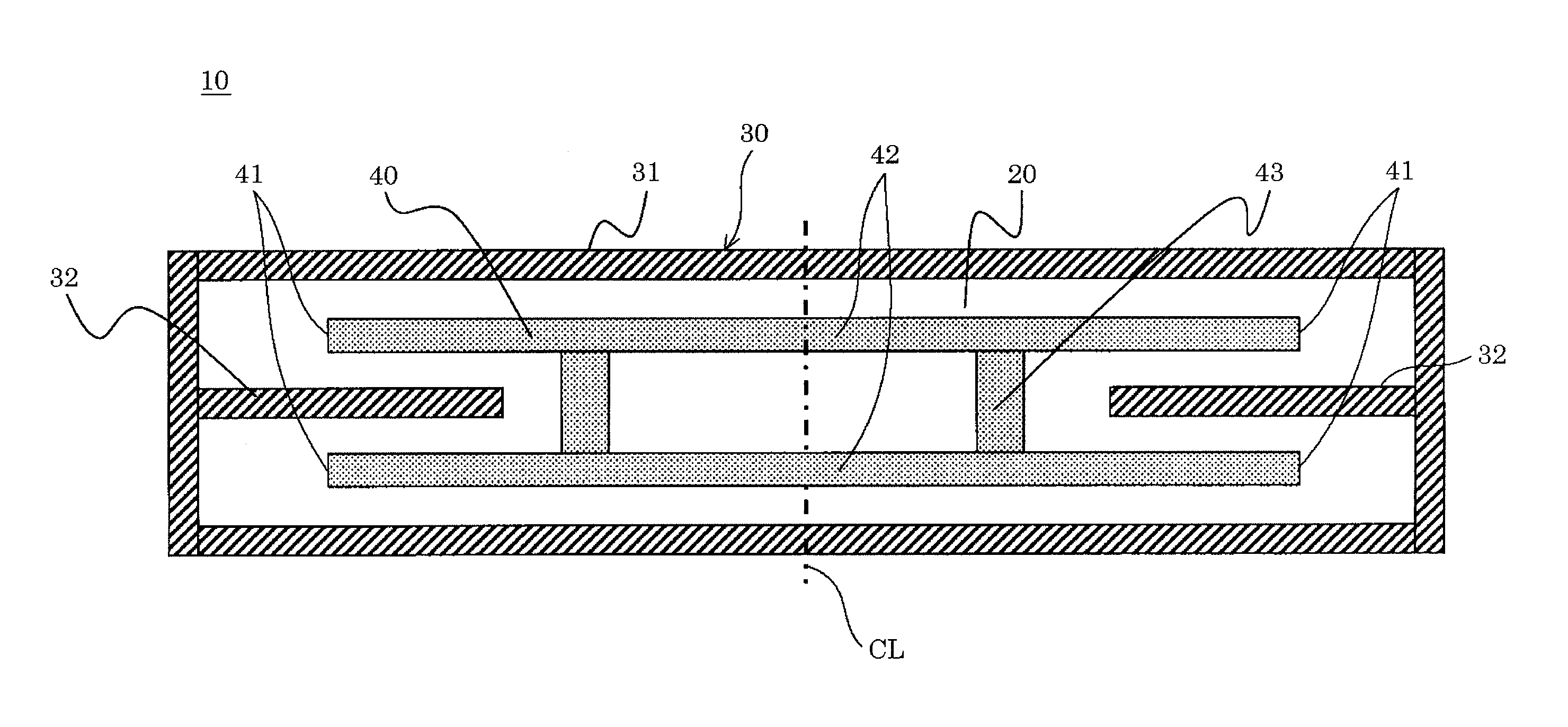
[0041]Next, the magnet unit 10 of the first embodiment mounted in the sputtering apparatus 1 will be described with reference to FIG. 4. FIG. 4 is a plan view showing a constitution of the magnet unit of the first embodiment.

[0042]As shown in FIG. 4, the magnet unit 10 of this embodiment includes a yoke 20 on the back side of the cathode electrode. The yoke 20 has the same shape (rectangular shape) as the target 6 and is formed of a ferromagnetic plate material. The yoke 20 includes thereon with an annular peripheral magnet 30 disposed along the contour of the target 6 and an inner magnet 40 disposed in the peripheral magnet 30 and having a polarity different from the polarity of the peripheral magnet 30.

[0043]As described above, a main body (a first magnetic pole) 31 of the peripheral magnet 30 is formed into an annular shape (a rectangular frame shape) so as to follow the contour of the target 6.

[0044]The inner magnet 40 disposed in the main body (the first magnetic pole) 31 of th...

second embodiment

[0055]Next, a magnet unit 50 of a second embodiment mounted in the sputtering apparatus 1 will be described with reference to FIG. 7. FIG. 7 is a plan view showing a constitution of the magnet unit of the second embodiment. In the following description of the second embodiment, the same components as those in the first embodiment are assigned with the same reference numerals.

[0056]As shown in FIG. 7, in the magnet unit 50 of the second embodiment, a yoke 20 and a peripheral magnet 30 each have the same structure as those of the first embodiment. Namely, the magnet unit 50 includes the yoke 20 on the back side of the cathode electrode. The yoke 20 has the same shape (rectangular shape) as a target 6 and is formed of a ferromagnetic plate material. A main body (a first magnetic pole) 31 of the peripheral magnet 30 is formed into a rectangular frame shape so as to follow the contour of the target 6. The main body (the first magnetic pole) 31 of the peripheral magnet 30 has on the insid...

example 1

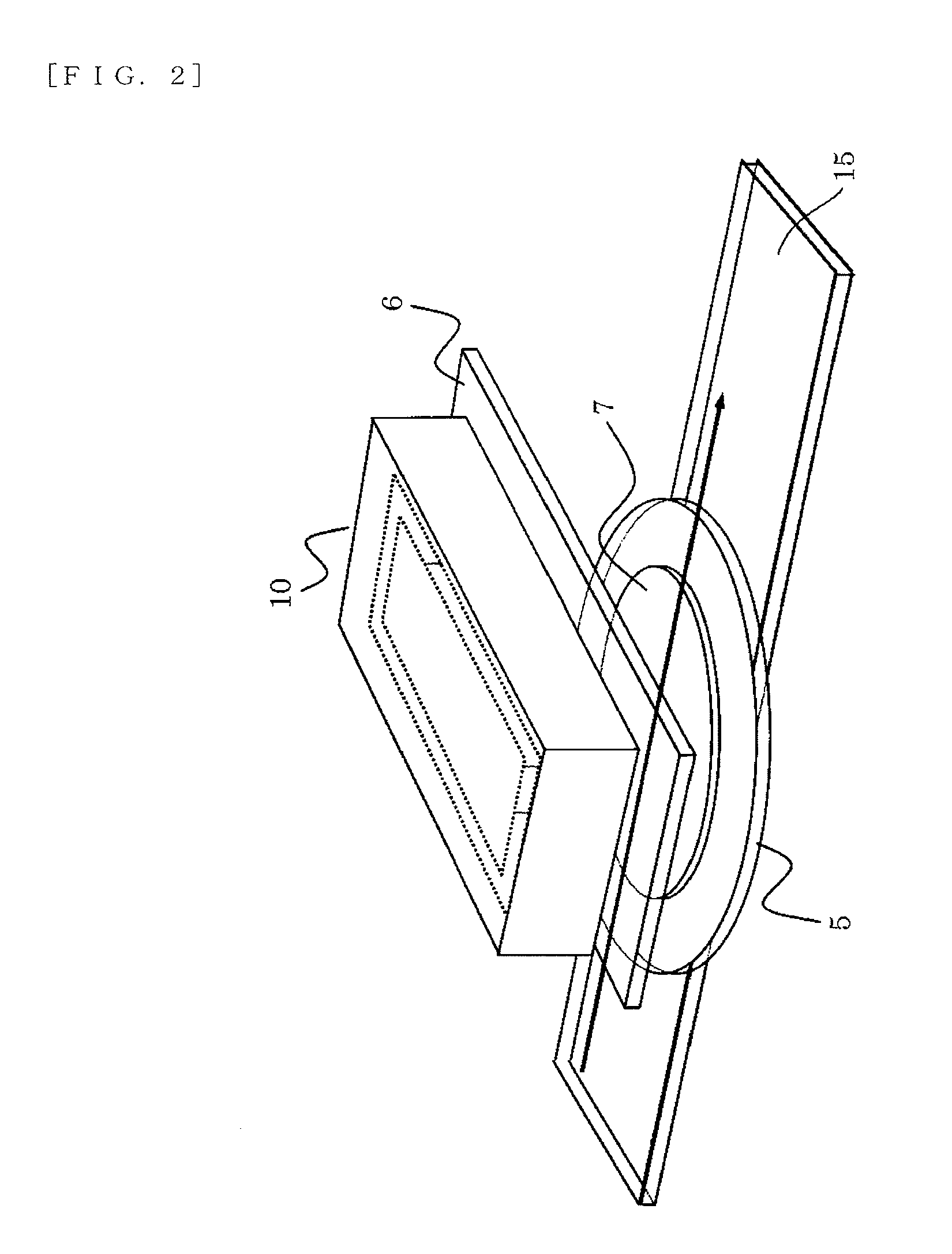
[0068]In an example 1, the sputtering apparatus 1 of FIG. 1 and the conveyance mechanism (guide rail) 15 of FIG. 2 are used, a plurality of silicon substrates are supported on the guide rail, the guide rail is moved in a direction perpendicular to the longitudinal direction of a target, and a titanium nitride film is then formed on each substrate.

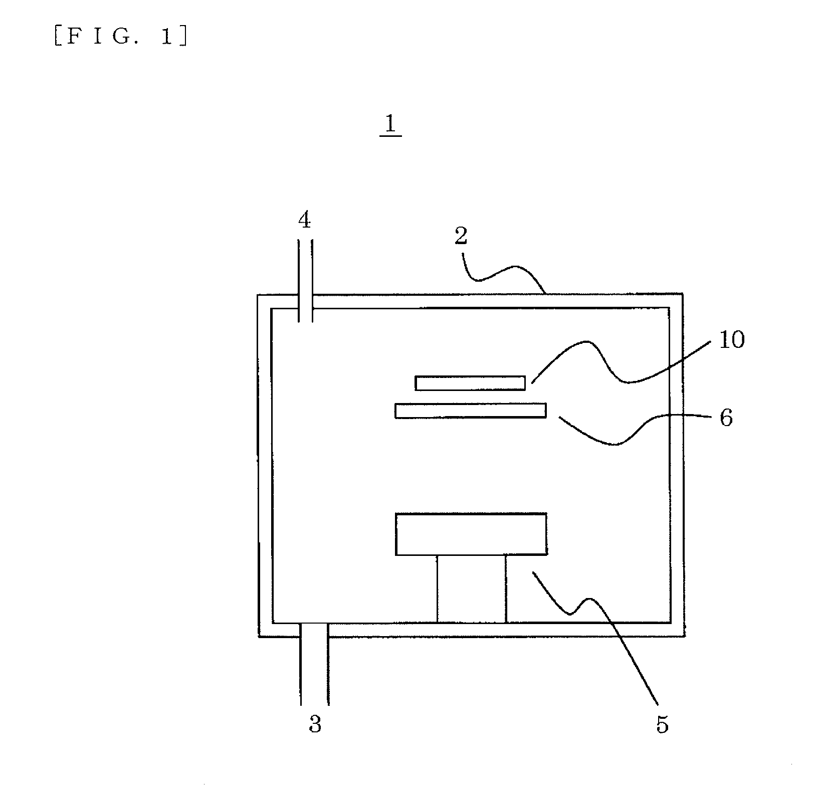
[0069]Titanium (Ti) is used as the target 6 supported by a cathode electrode, and a mixed gas composed of Ar and N2 as a process gas is introduced into the vacuum vessel 2.

[0070]FIG. 10 is an explanatory view showing the film-formation conditions in the example 1, comparing with the prior art technique. As shown in FIGS. 10A and 100, when the prior art magnet unit is mounted in the sputtering apparatus 1, the film thickness of the peripheral portion of the substrate corresponding to the both ends in the longitudinal direction of the target 6 is reduced.

[0071]Meanwhile, as shown in FIGS. 10B and 10D, when the magnet unit 10 is mounted in the...


PUM

PropertyMeasurementUnit
polarityaaaaaaaaaa
magnetic fieldaaaaaaaaaa
magneticaaaaaaaaaa

Abstract

A magnet unit, which can realize uniform film thickness distribution of a thin film formed on a substrate without increasing the length and width of a target. The magnet unit includes a peripheral magnet, which is disposed on the yoke on the back side of a cathode electrode so as to follow the outline of a target, and an inner magnet disposed in the peripheral magnet and having a polarity different from the polarity of the peripheral magnet. The magnet unit provides a magnetic track MT that is a set of regions which tangents of magnetic field lines M generated on the target parallels to the target surface. The magnet unit further includes n (n is a positive integer of two or more) extending magnetic pole portions and n−1 projecting magnetic pole portions, which form 2n−1 folded shape portions U at the both ends in the longitudinal direction of the magnetic track.

Description

[0001]This application is a National Stage Entry under 35 U.S.C. §371 of International Application No. PCT / JP2009 / 003206, filed on Jul. 9, 2009, the content of which is incorporated herein by reference in its entirety.TECHNICAL FIELD[0002]The present invention relates to an improvement of a structure of a magnet unit disposed on the back side of a cathode electrode supporting a target on the front side in sputtering and a magnetron sputtering apparatus including the magnet unit.BACKGROUND ART[0003]In a magnetron sputtering apparatus, a magnet unit disposed on the back side of a cathode electrode supporting a target causes generation of magnetron on a discharge surface of the target to entrap a plasma, and, thus, to realize high density. Then, ions of the plasma generated in this apparatus collide with the target to thereby flick a target material. The target material is then adhered onto a substrate, whereby a thin film is formed.[0004]Thus, a film formation rate strongly depends on...

Claims


Application Information

Patent Timeline
Patent Type & Authority Patents(United States)
IPC IPC(8): C23C14/35
CPCC23C14/35H01J37/3452H01J37/3405
Inventor ENDO, TETSUYAABARRA, EINSTEIN NOEL
Owner CANON ANELVA CORP
Why Eureka
Try Eureka