
Waste processing system, machine and method thereof

a technology of waste processing and waste, applied in the field of waste processing machines, can solve the problems of inability to power these machines, noise, emissions, etc., and achieve the effects of reducing production costs, reducing production costs, and reducing production costs

Active Publication Date: 2012-09-20
BANDIT IND
View PDF1 Cites 21 Cited by
  • Summary
  • Abstract
  • Description
  • Claims
  • Application Information

AI Technical Summary

Benefits of technology

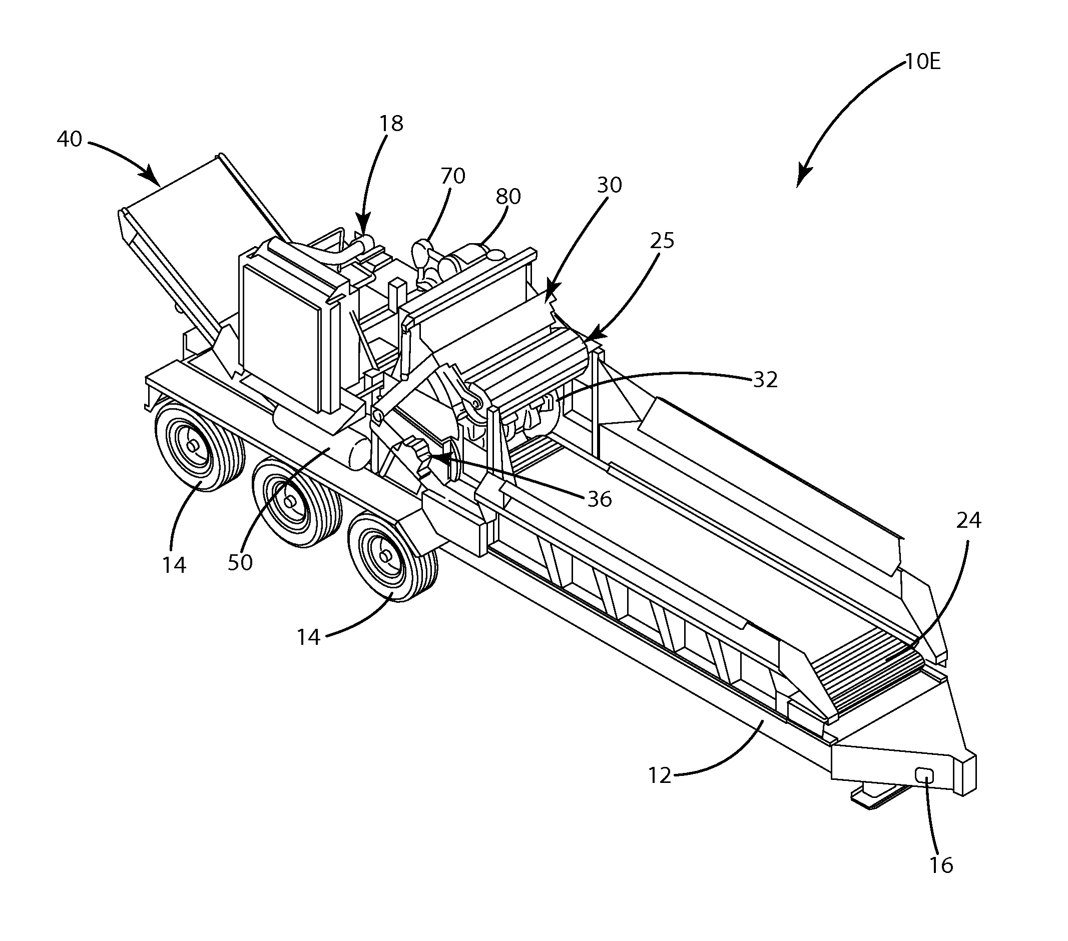
[0011]The aforementioned drawbacks and disadvantages of these former waste processing machines have been identified and a solution is set forth herein by the inventive waste processing machine which includes a waste processing machine for reducing wood material which comprises a power system and a cutting system. Also disclosed is a an accumulator which is adapted to receive, store, and release energy (e.g., a charge, form of energy, power), wherein the accumulator is operatively connected to at least one of the power system and the cutting system and is adapted to provide the energy or charge to at least one of the power system and the cutting system, for example, upon discharge thereof. Also disclosed is a charging device for producing the energy or charge and which charges the accumulator with the energy or charge, wherein the charging device is operatively connected to the accumulator and operatively connected to at least one of the power system and the cutting system. Further, the charging device is adapted to produce the charge in response to the at least one of the power system and the cutting system, for example, when operated, whereby the accumulator is adapted to provide the energy or charge stored therein to the at least one of the power system and the cutting system.

Problems solved by technology

In these prior art systems, while the internal combustion engine offers many known advantages, these prior art engines also suffer from several problems.
As most existing systems are powered by either gasoline or diesel engines, and as the costs and known problems associated with petroleum powered products increase, so to do the problems associated with the operation of these waste machines.
For example, the disadvantages of these known systems include, inter alia, emissions, noise; reliance on volatile fuel products, and consumption.
Additionally, it is not practical to power these machines only when the reducing operation is needed or takes place as these waste machines require additional energy and time in which to place the machine into the running or at-speed mode (e.g., to place the machine in or obtain the desired operational characteristics).
As such, it is not practical to shut these machines down during the interim periods of time when the reduction systems are not being utilized to reduce bulk wood products, but the overall reduction process is still required.
At these times, in most applications, these machines remain powered and are thereby consuming resources even though the actual reduction operation is not occurring.
Further, these machines consume more energy when the demand on the machine is high, than they do at other times of operation (e.g., when not under load or processing).
For example, when the demand on the cutting head is high, as when reducing heavy loads, the power consumption of the machine may increase or spike.
Yet further, these higher powered engines are typically also noisier, costlier to fix and maintain, and more difficult to repair than their smaller counterparts.

Method used


Image

  • Waste processing system, machine and method thereof
  • Waste processing system, machine and method thereof
  • Waste processing system, machine and method thereof

Examples


Embodiment Construction

[0043]The best mode for carrying out the invention is presented in terms of the preferred embodiment, wherein similar referenced characters designate corresponding features throughout the several figures of the drawings.

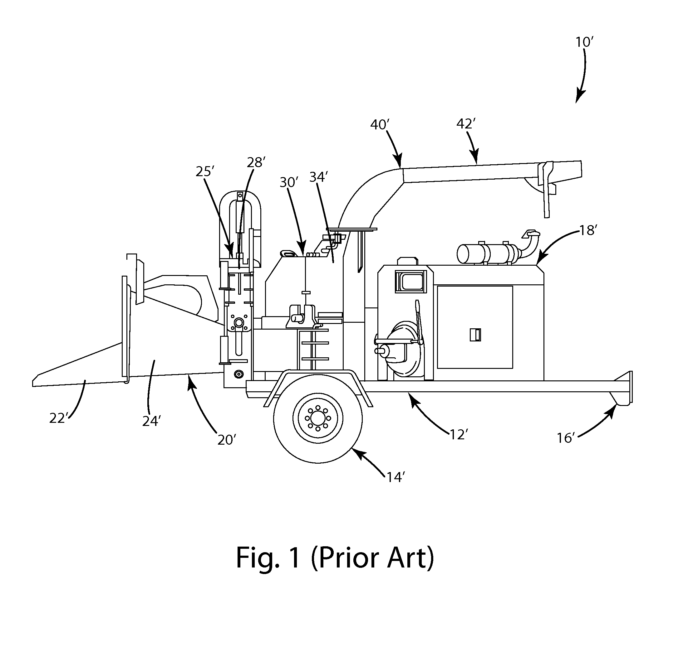
[0044]For purposes of description herein, the terms “upper”, “lower”, “right”, “left”, “rear”, “front”, “vertical”, “horizontal”, and derivatives thereof, shall relate to the invention as oriented in FIG. 1. However, it is to be understood that the invention may assume various alternative orientations, except where expressly specified to the contrary. It is also to be understood that the specific devices and processes illustrated in the attached drawings and described in the following specification are exemplary embodiments of the inventive concepts defined in the appended claims. Hence, specific dimensions and other physical characteristics relating to the embodiments disclosed herein are not to be considered as limiting, unless the claims expressly state otherwise....


PUM

PropertyMeasurementUnit
electrical chargeaaaaaaaaaa
hydraulic chargeaaaaaaaaaa
pressureaaaaaaaaaa

Abstract

a waste processing machine for reducing wood waste comprises an accumulator operatively connected to the cutting system so as to power the cutting system upon discharge thereof. The accumulator is adapted to receive, store, and release a charge developed from a charging device operatively connected to the accumulator and one or more systems of the waste processing machine.

Description

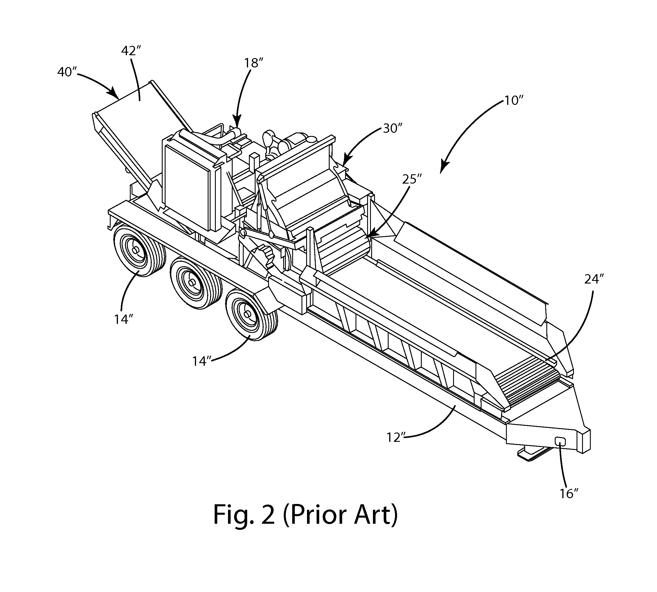
CROSS REFERENCE TO RELATED APPLICATIONS[0001]This application claims the benefit of the filing date of U.S. provisional application Ser. No. 61 / 426,652 entitled “Hybrid Waste Processing System, Machine and Method thereof” which was filed on Dec. 23, 2010 and which is incorporated herein by reference in its entirety.BACKGROUND OF THE INVENTION[0002]The present invention relates to waste processing machines, and more specifically to waste processing machines for processing wood such as brush, branches, and the like.[0003]A variety of machines have been developed to recycle, reduce, or otherwise process wood and brush products. Included therein are machines that chip, cut, grind, or otherwise reduce waste (wood) products including, generally, chippers (disk and drum types), hammer mills, hogs, shredders, grinders, and forestry mowers.[0004]These waste processing machines and systems typically include an infeed system and a waste reducing system, wherein the infeed system is used for di...

Claims


Application Information

Patent Timeline
Patent Type & Authority Applications(United States)
IPC IPC(8): B02C18/24B02C23/02B27L11/00B02C25/00
CPCA01G3/002B02C18/24B02C25/00
Inventor MOREY, MICHAEL BOYD
Owner BANDIT IND
Learn More