Inkjet head, inkjet recording apparatus, liquid droplet ejecting apparatus, and image forming apparatus

Active Publication Date: 2012-09-20
RICOH KK
View PDF0 Cites 46 Cited by
  • Summary
  • Abstract
  • Description
  • Claims
  • Application Information

AI Technical Summary

Benefits of technology

[0014]The present invention makes it possible to realize and provide a novel inkjet head, an inkjet recording apparatus, a liquid droplet ejecting apparatus, and an image forming apparatus that solves the above-described problems to achieve the above-described objects.
[0015]In other words, with the features as described above, embodiments of the present invention may prevent deterioration of a piezoelectric material due to moisture within the atmosphere and plasma in the above-described semiconductor process and increase an amount of displacement of a piezoelectric element and, at the same time, eliminate constraints of wiring of a dedicated electrode, etc., to realize and provide an injection head which may be made highly dense, or in other words, to realize and provide a small-sized injection head while maintaining high reliability (moisture resistance) and superior ejection characteristics.
[0016]Moreover, with the features as described above, embodiments of the present invention m

Problems solved by technology

Moreover, besides the above-described plasma process, it is commonly known that the characteristics of the piezoelectric material deteriorate due to moisture within the atmosphere.
However, with the technique disclosed in Patent document 1, as the whole pattern area face including the piezoelectric element is covered with the inorganic amorphous material, making a film thick remarkably obstructs a displacement of the piezoelectric element, causing the ejection characteristics to deteriorate considerably.
On the other hand, making a thin film of the inorganic amorphous material in order to achieve a large amount of displacement of the piezoelectric element causes an inability to ensure withstand pressure between the lead electrode and the lower electrode.
Therefore, there is a problem that, as it is necessary to provide an electrode layout such that an overlap of the lead electrode and the lower electrode does not occur, making a head small and highly dense becomes difficult, and, at the same time, a constraint occurs on a height of a junction with a protective substrate, making an enhancement of the junction quality difficult.
In a device manufactured in a semi

Method used


Image

  • Inkjet head, inkjet recording apparatus, liquid droplet ejecting apparatus, and image forming apparatus
  • Inkjet head, inkjet recording apparatus, liquid droplet ejecting apparatus, and image forming apparatus
  • Inkjet head, inkjet recording apparatus, liquid droplet ejecting apparatus, and image forming apparatus

Examples


Example

Example 1

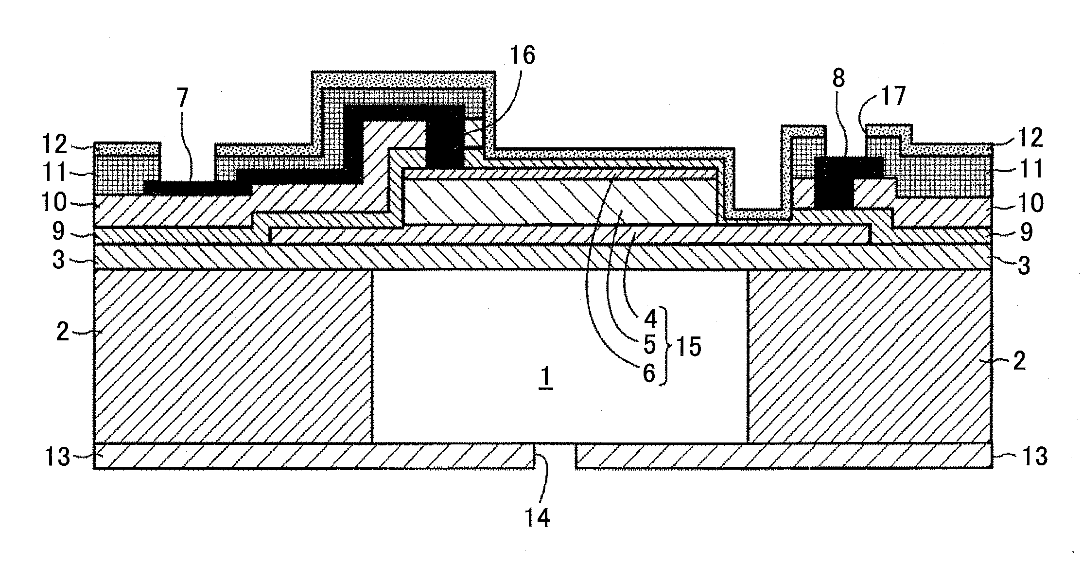
[0093]A thermal oxide film (with a film thickness of 1 micron) is formed on a silicon wafer, and, as a lower electrode, a titanium film (with a film thickness of 50 nm), a platinum film (with a film thickness 200 nm), and an SrRuO film (with a film thickness of 100 nm) are formed by sputtering. The titanium film serves as a cohesive layer between the thermal oxide layer and the platinum layer. Next, as an electromechanical conversion film, a film of PZT(53 / 47) is formed by spin coating. For synthesizing a PZT precursor applying solution, lead acetate trihydrate, titanium isopropoxide, and zirconium isopropoxide may be used. Combined water of lead acetate dissolves in methoxyethanol, after which it dehydrates. An amount of lead relative to the stoichiometric composition is arranged to be 10 mol % excess. This is to prevent a drop in crystallinity due to a so-called lead drop during the thermal process. Titanium isopropoxyde and zirconium isopropoxide are dissolved in methoxy...

Example

Example 2

[0097]Other than forming a 20 nm film of Al2O3 of the insulating films 9 and 12, an inkjet head (element) is manufactured as in Example 1.

Example

Example 3

[0098]Other than forming a 100 nm film of Al2O3 of the insulating films 9 and 12, an inkjet head (element) is manufactured as in Example 1.


PUM


Abstract

An inkjet head is disclosed. In the inkjet head a vibrating plate is formed on a liquid chamber substrate on which multiple dedicated liquid chambers are aligned; a first insulating film and a second insulating film are formed between a dedicated electrode wiring and a lower electrode in an area in which the dedicated electrode wiring and the lower electrode overlap; a third insulating film and a fourth insulating film are stacked in an area which includes a forming area of the dedicated electrode wiring; in at least a portion of a forming area of the dedicated liquid chamber, there is provided a non-film forming area; and, in an area including a piezoelectric element forming section, either the first insulating film and the fourth insulating film are formed in the non-film forming area, or the fourth insulating film is formed in the non-film forming area.

Description

TECHNICAL FIELD[0001]The present invention generally relates to inkjet heads, inkjet recording apparatuses, liquid droplet ejecting apparatuses, and image forming apparatuses, and specifically relates to image forming apparatuses; and inkjet heads, inkjet recording apparatuses, and liquid droplet ejecting apparatuses for use in the image forming apparatuses such as printing machines including a copying machine, a facsimile machine, a printer, a plotter, and a screen printing machine; and multi-functional machines which include multiple of the above-described functions.BACKGROUND ART[0002]As a technique to increase a density of an inkjet head using a piezoelectric element, a technique is known and embodied which applies a micro electromechanical system (below abbreviated as “MEMS”). In other words, a semiconductor device manufacturing technique may be applied and an actuator and a liquid flow path may be minutely formed to increase a nozzle density, making it possible to realize a re...

Claims


Application Information

Patent Timeline
IPC IPC(8): B41J2/045
CPCB41J2/14274B41J2/1612B41J2/1628B41J2/1629B41J2002/14491B41J2/1642B41J2/1645B41J2/1646B41J2/1631
Inventor MIZUKAMI, SATOSHIKATO, MASAKIKURODA, TAKAHIKOABE, KANSHIAKIYAMA, YOSHIKAZU
Owner RICOH KK
Why Eureka
Try Eureka