Multistate-curvature device and method for delivering a curable material into bone

Active Publication Date: 2012-09-20
STRYKER CORP
View PDF5 Cites 67 Cited by
  • Summary
  • Abstract
  • Description
  • Claims
  • Application Information

AI Technical Summary

Benefits of technology

[0011]Embodiments disclosed herein may include a delivery cannula providing a non-traumatic, blunt distal end that minimizes the risks of coring tissue or puncturing bone or tissue during intraosseous procedures without requiring additional components (such as separate wire). Certain embodiments relate to vertebroplasty systems including guide cannula, delivery cannula, which may be embodied as a needle and that may be formed of or at least include a memory metal, where the memory metal is configured to be generally straight at ambient temperature and to be manipulable to at least a first curve at a first higher selected temperature and a second curve at a second higher selected temperature. Certain embodiments may relate to a delivery cannula defining at least one side orifice adjacent to a blunt distal end, where the orifice(s) permit a radial infusion of a curable material at a site

Problems solved by technology

With the above in mind, because the needle cannula interacts with the cancellous bone and other soft tissue structures, an inherent risk exists that following initial insertion, the needle cannula might core or puncture other tissue and/or the bone mass being repaired (at a location apart from the insertion site).
Unfortunately, for many procedures, the surgical site in question cannot be fully accessed using a conventional, straight needle cannula.
Further, the needle can only dispense the stabilizing material through the axial opening at the distal tip of the needle, perhaps impeding a surgeon's ability to infuse all desired areas and/or requiring an additional procedural step of “backing” the needle tip away from the desired delivery site.
Also, because the needle tip, and thus the axial opening, is likely at or facing the bone defect (e.g., fracture in the vertebral body) being repaired, the stabilizing material may be injected directly

Method used


Image

  • Multistate-curvature device and method for delivering a curable material into bone
  • Multistate-curvature device and method for delivering a curable material into bone
  • Multistate-curvature device and method for delivering a curable material into bone

Examples


Embodiment Construction

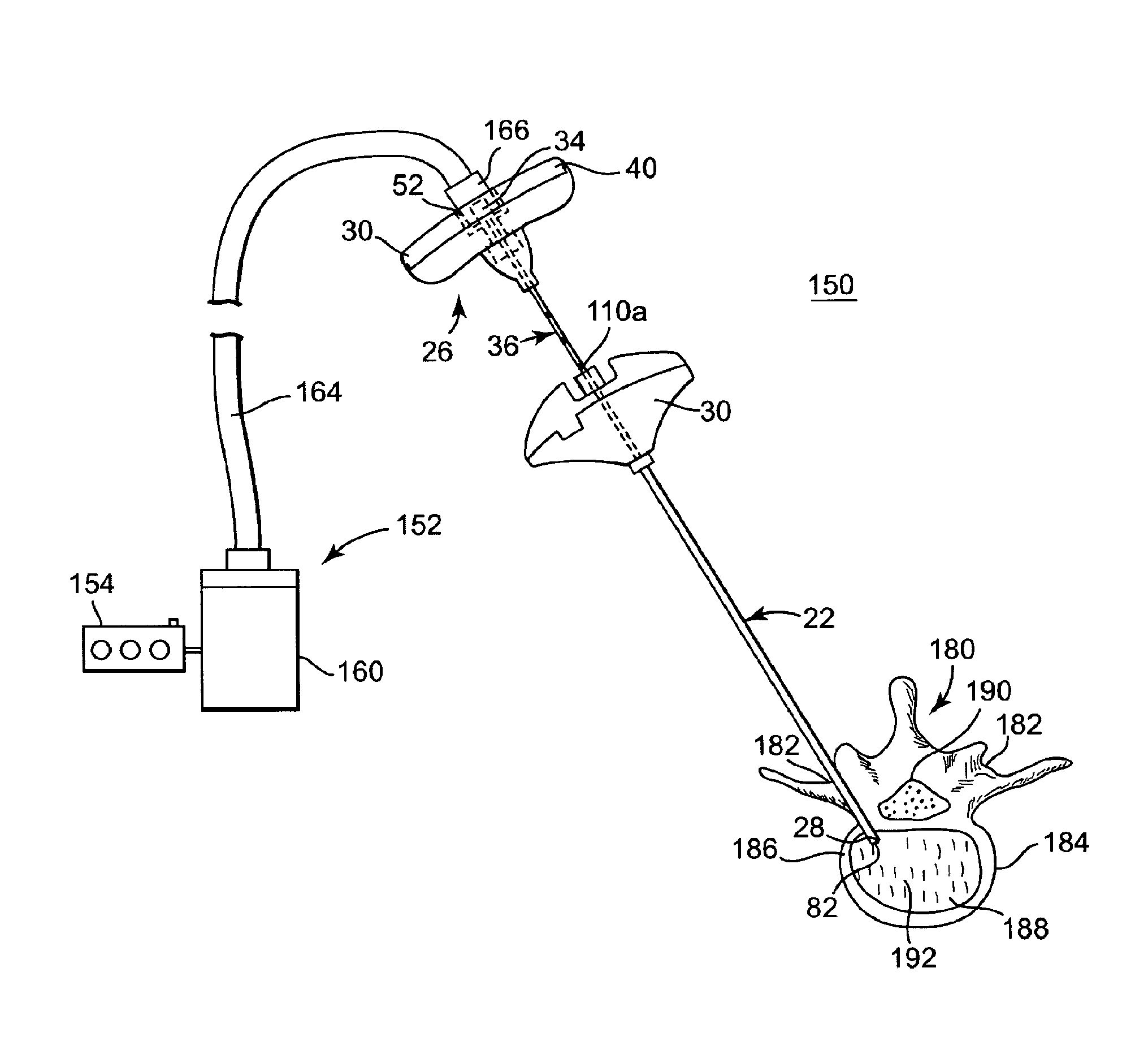
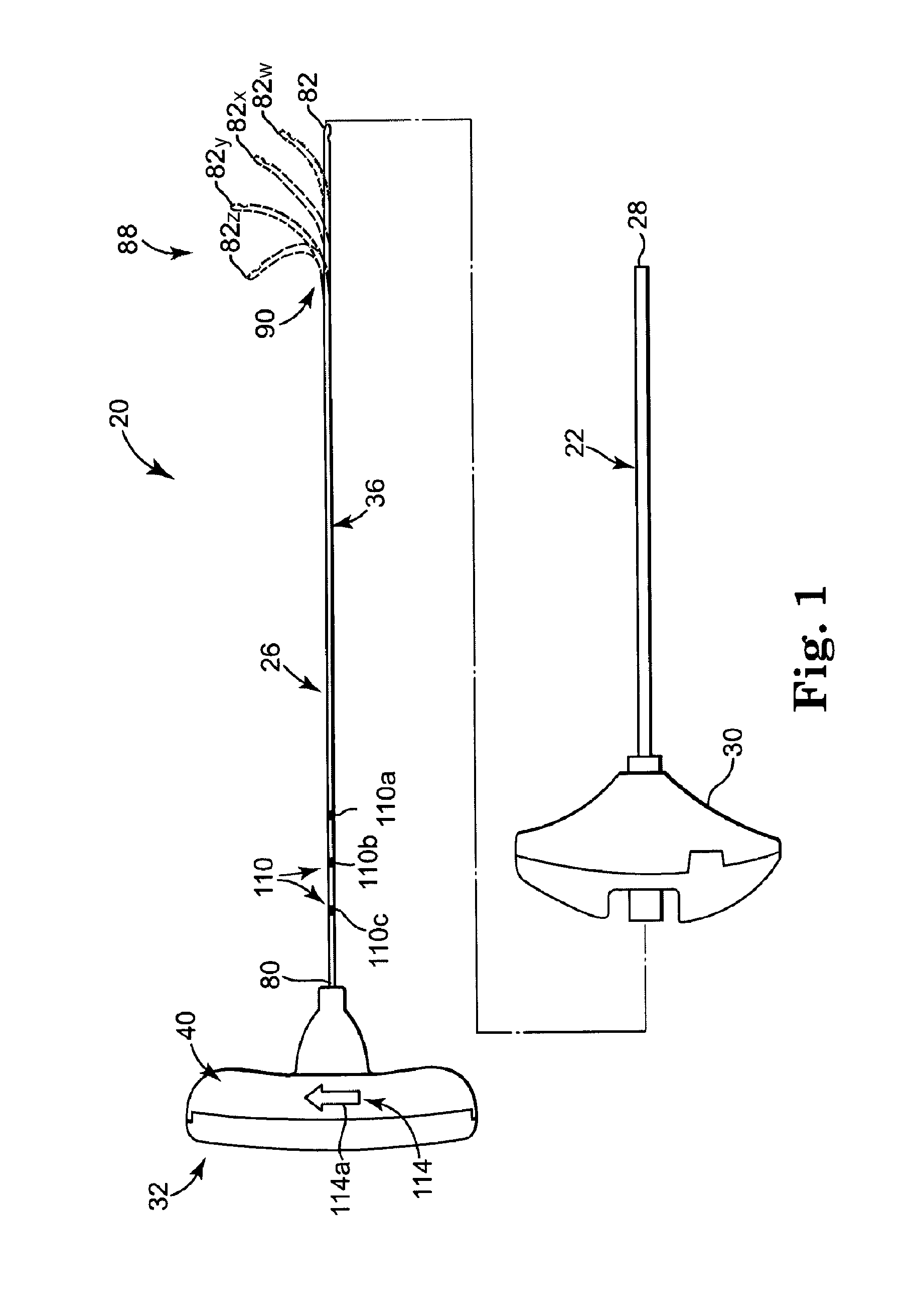
[0039]FIG. 1 illustrates components of an intraosseous, curable material delivery system 20. The system 20 includes an outer guide cannula 22 and a delivery cannula device 26 (referenced generally). Details on the various components are provided below. In general terms, however, a portion of the delivery cannula device 26 is sized to be slidably disposed within the guide cannula 22 that otherwise serves to form and / or locate a desired delivery site within bone. After it is positioned through the guide cannula lumen, the delivery cannula device 26 may be employed to inject a curable, bone stabilizing material into the delivery site. The system 20 can be used for a number of different procedures, including, for example, vertebroplasty and other bone augmentation procedures in which curable material is delivered to a site within bone, as well as to remove or aspirate material from a site within bone.

[0040]The system 20, and in particular the delivery cannula device 26, is highly useful...


PUM


Abstract

A curable material delivery cannula device and method are disclosed. The device includes a cannula and a hub. The cannula includes an open proximal end, a deflectable segment forming a plurality of pre-set curves, each of which corresponds to a pre-determined temperature of the cannula, a lumen, and side orifice(s) adjacent, and proximally spaced from, the distal end and fluidly connected to the lumen. When distally extended from the guide cannula, and upon being heated to a predetermined temperature (before, during, or after extension), the deflectable segment assumes a curved shape, which may be used to create a void in the bone for receiving curable material. The distal cannula end includes a blunt tip for non-traumatic interface with bodily material. During use, curable material, such as bone cement, is delivered from the side orifice(s) in a radial direction relative to the lumen.

Description

RELATED APPLICATIONS[0001]This application is a continuation in part of co-pending U.S. patent application Ser. No. 12 / 633,358, filed Dec. 8, 2009, which is a divisional of U.S. Pat. No. 7,799,035, which is a continuation-in-part of U.S. Pat. No. 7,713,273, each of which is incorporated by reference herein in its entirety, and to which priority is claimed.TECHNICAL FIELD[0002]The present invention relates to devices and methods for stabilizing bone structures. More particularly, it relates to systems and methods for delivering a curable, stabilizing material into a bone structure.BACKGROUND[0003]Surgical intervention at damaged or compromised bone sites has proven highly beneficial for patients, for example patients with back pain associated with vertebral damage.[0004]Bones of the human skeletal system include mineralized tissue that can generally be categorized into two morphological groups: “cortical” bone and “cancellous” bone. Outer walls of all bones are composed of cortical b...

Claims


Application Information

Patent Timeline
IPC IPC(8): A61B17/88A61F2/28
CPCA61B17/1604A61B17/1671A61B17/3421A61B17/3472A61B17/8811A61B2019/462A61B17/8836A61B2017/00331A61B2017/00455A61B2017/00867A61B17/8819A61B2090/062
Inventor LINDERMAN, EVAN D.RAY, JOHN
Owner STRYKER CORP
Why Eureka
Try Eureka