
Surge arrestor condition monitoring

a surge arrester and health condition technology, applied in the direction of instruments, electric digital data processing, emergency protective arrangements for limiting excess voltage/current, etc., can solve the problems of surge arrester health condition tending to deteriorate with time, low resistance under abnormally high voltage, thermal runaway

Inactive Publication Date: 2012-09-20
RAYCHEM INT IRISH BRANCH
View PDF3 Cites 30 Cited by
  • Summary
  • Abstract
  • Description
  • Claims
  • Application Information

AI Technical Summary

Benefits of technology

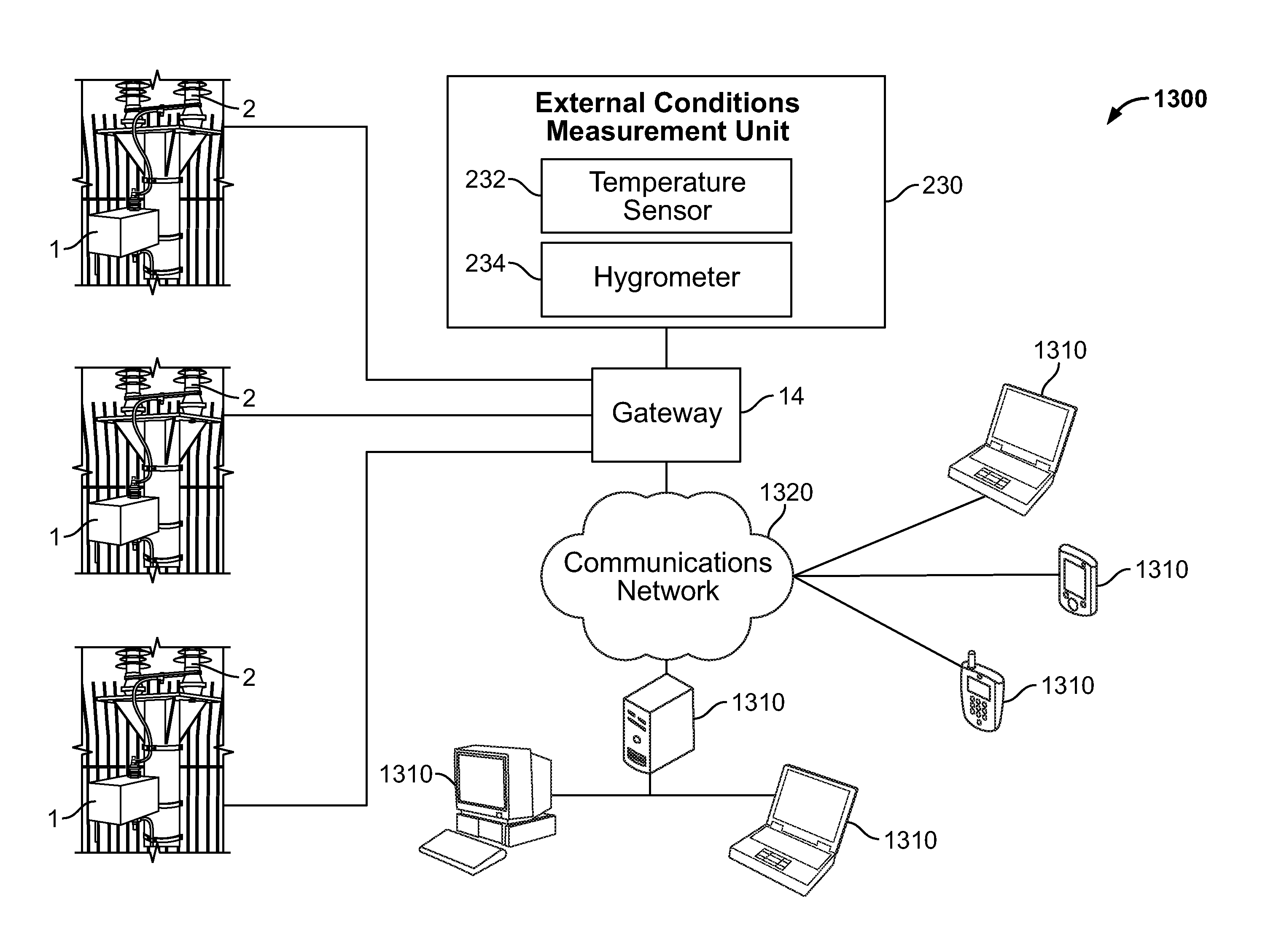
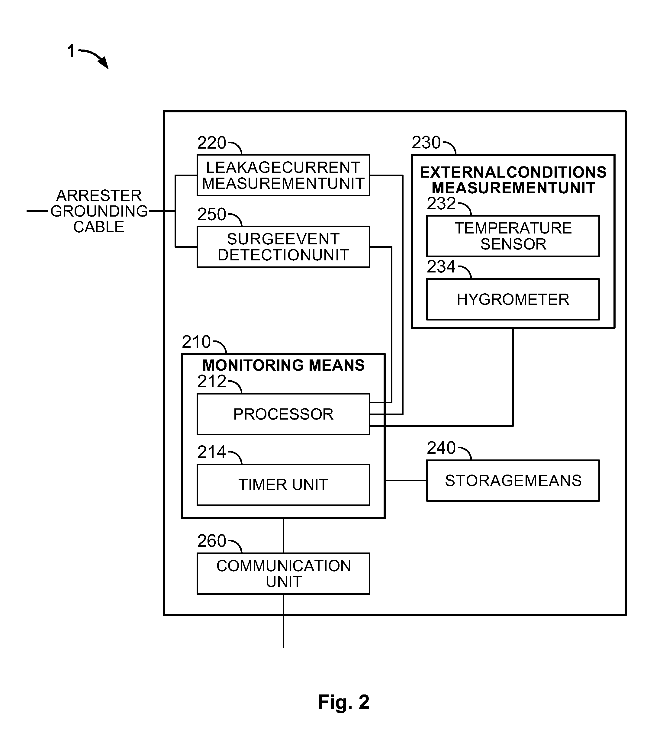
"The present invention provides a monitoring device, system, and method for monitoring the condition of a surge arrester. The monitoring device includes a monitoring means for monitoring the leakage current of the surge arrester over a monitoring period, including a recovery monitoring period after a surge event. The amount of time taken for the leakage current to return to its normal level is a powerful indicator on the arrester's ability to recover from the surge discharge. The monitoring reporting device can generate a report based on the monitoring data and send it to an operator for evaluation and identification of the arrester condition. The monitoring system allows multiple surge arresters to be monitored simultaneously and remotely, increasing safety and convenience for the operator. The method involves acquiring monitoring data, generating report data, and reporting it."

Problems solved by technology

However, in spite of their high reliability, the health condition of surge arresters tends to deteriorate with time, namely, due to excessive surge events, the amplitude of the discharging surge currents, etc.
For instance, a common type of lightning arresters used in power networks comprises a core of nonlinear resistance discs stacked inside a ceramic or polymeric casing that collectively functions as an insulator at normal operation voltages, with leakage currents of the order of the microampere, but exhibits very low resistance under an abnormally high voltage.
However, the gradual deterioration of the nonlinear resistance with time leads to an increase of the leakage current, which when surpasses a certain threshold value, for example in the multi-milliampere range, may cause thermal runaway followed by the thermal destruction of the arrester.
This technique however has the disadvantage that it does not allow to accurately monitor deterioration of the non-linear resistance discs since the total leakage current that includes both the leakage current flowing through the non-linear resistance discs and the leakage current flowing down along the flanged surface of the ceramic casing.
Further, since the external ambient conditions are variable, the current flowing along the ceramic casing may vary significantly and provide a false indication of the surge arrester condition.
However, since this technique relies on the special design of the surge arrester it is obviously not suitable for monitoring other types of surge arresters.
However, these techniques have the disadvantage that the monitoring devices are costly and require a high degree of experience for correctly measuring and interpreting the measured values.
In addition, some of these devices require auxiliary power supply and are therefore not suitable for continuous long-term monitoring on arresters.
However, such techniques have the inconvenience that they do not monitor the actual operation condition of the surge arrester.
They also do not take into consideration other factors that influence the condition of the arrester, such as energy discharged during the surge event.
However, it has the inconvenient that it cannot be used for other type of surge arresters.
In addition to the disadvantages mentioned above, existing techniques based on monitoring total leakage current or the third harmonic component of the leakage current rely on simply monitoring these parameters at isolated instants of time and making periodic comparisons of this data irrespective of the number of surge events that might have occurred in between.
They do not allow to correlate the monitored values with the respective surge events, for instance, duration and amplitude of the surge discharge, which also have an influence on the deterioration of the surge arrester condition.
Existing monitoring techniques also do not allow to identify and report the deterioration of the surge arrester condition shortly after the occurrence of a surge event.

Method used


Image

  • Surge arrestor condition monitoring
  • Surge arrestor condition monitoring
  • Surge arrestor condition monitoring

Examples


Embodiment Construction

[0052]Advantageous embodiments of the present invention will now be described in further detail with reference to the accompanying drawings.

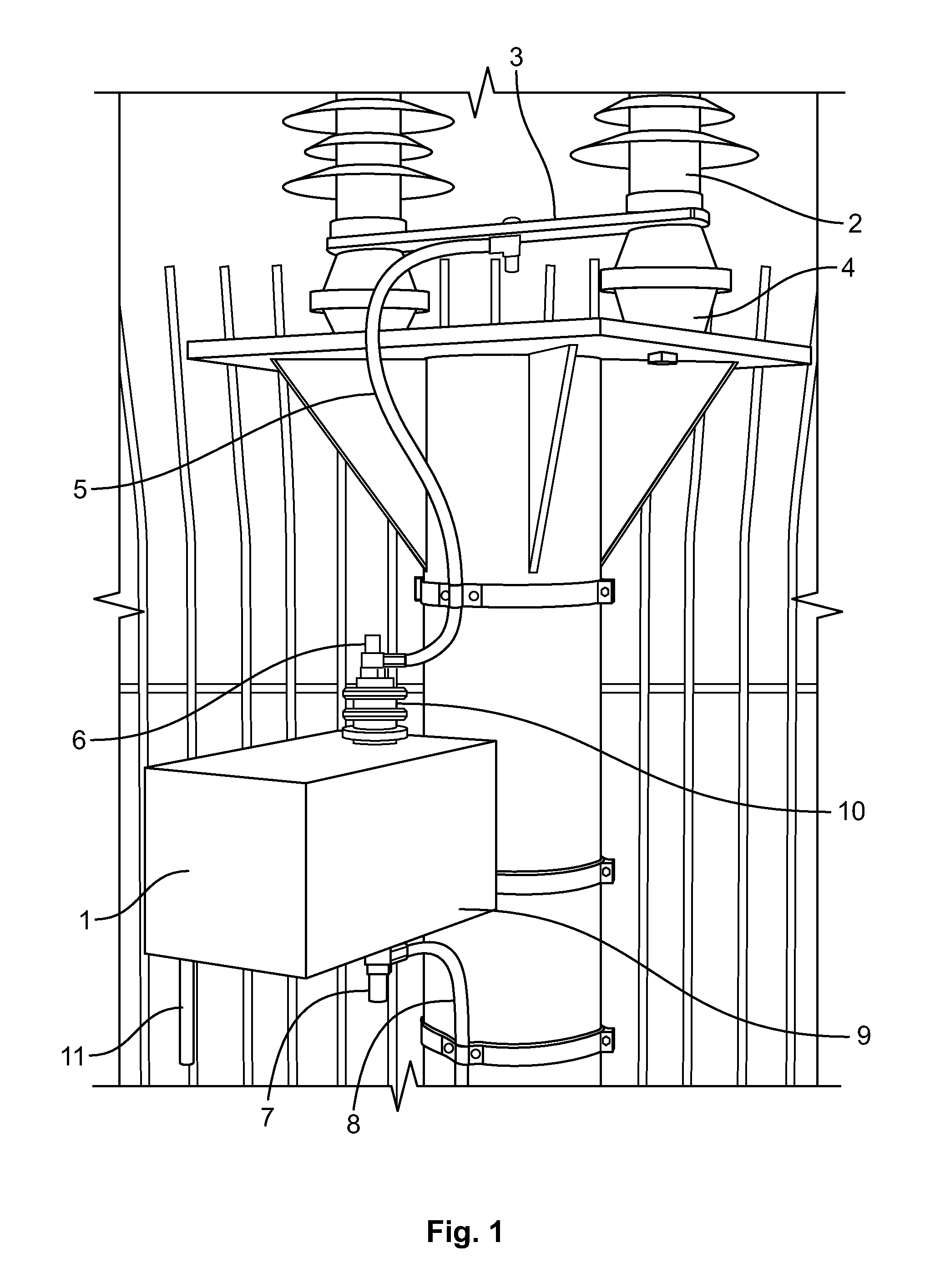
[0053]FIG. 1 shows a monitoring device 1 according to the present invention already installed in a surge arrester 2 to be monitored.

[0054]The illustrated surge arrester 2 is of the vertical type, having a lower part 3 made of an electrical conducting material that rests on a number of insulating bases 4 or supports. A surge arrester grounding cable 5, or simply grounding line, is connected to the lower part 3 for allowing the surge arrester leakage current to flow to the ground.

[0055]The monitoring device 1 of the invention is nevertheless adapted to monitor surge arresters having configurations other than the one illustrated in FIG. 1.

[0056]The monitoring device 1 is intended to be installed in the proximity of the surge arrester 2 to be monitored and to remain electrically connected to the surge arrester 2 during the arrester working life such...


PUM


Abstract

A monitoring device (1) for monitoring a condition of a surge arrester comprises monitoring means (210) adapted to monitor a leakage current recovery of the surge arrester after an occurrence of a surge over a recovery monitoring period following the surge event. The monitoring of recovery of surge arrester leakage current following the surge event in the arrester is used to estimate the time to recovery of the leakage currents and to identify a deterioration in the condition of the arrester by comparing the evolution of the time to recovery over time.

Description

TECHNICAL FIELD OF THE INVENTION[0001]The present invention relates to the monitoring of the health condition of surge arresters, more specifically, to the monitoring of surge arrester leakage currents as a means of determining changes in the health of a surge arrester overtime.BACKGROUND OF THE INVENTION[0002]Surge arresters, also referred to as lightning arresters, are commonly used for protecting power networks and sensitive equipment against incoming overvoltages caused by lightning and / or switching surges.[0003]However, in spite of their high reliability, the health condition of surge arresters tends to deteriorate with time, namely, due to excessive surge events, the amplitude of the discharging surge currents, etc.[0004]For instance, a common type of lightning arresters used in power networks comprises a core of nonlinear resistance discs stacked inside a ceramic or polymeric casing that collectively functions as an insulator at normal operation voltages, with leakage current...

Claims


Application Information

Patent Timeline
Patent Type & Authority Applications(United States)
IPC IPC(8): G06F19/00G01R31/02
CPCH02H9/042H02H1/0092H02H1/0061
Inventor NORMOYLE, BRENDANFITZGERALD, PADRAIGLEYDEN, MARKBOUCHE, JEAN-CHRISTOPHE
Owner RAYCHEM INT IRISH BRANCH
Learn More