Control device, control system, and control method

a control system and control device technology, applied in the integration of power network operation systems, electric devices, instruments, etc., can solve the problems of increasing the power consumption of consumers, above-mentioned conventional technology does not consider the electric power demand of a consumer group and an electric power supply,

Inactive Publication Date: 2012-09-20
KYOCERA CORP
View PDF14 Cites 18 Cited by
  • Summary
  • Abstract
  • Description
  • Claims
  • Application Information

AI Technical Summary

Benefits of technology

[0017]According to the present invention, it is possible to perform appropri

Problems solved by technology

However, the above-mentioned conventional technology does not consider an electric power demand of a consumer group and an electric power supply from an electric power system.
This led to a problem that even when the electric power supply from the electric power system exceeds the electric power demand of

Method used


Image

  • Control device, control system, and control method
  • Control device, control system, and control method
  • Control device, control system, and control method

Examples


Embodiment Construction

[0025]Hereinafter, an embodiment of the present invention will be described with reference to the accompanying drawings. Specifically, the embodiment of the present invention will be described in sequence of (1) Configuration of electric power system, (2) Operation of electric power system, (3) Operation and effect, and (4) Other embodiments. In all drawings for explaining the following embodiments, the same or similar reference numerals are used to designate the same or similar elements.

(1) Configuration of Electric Power System

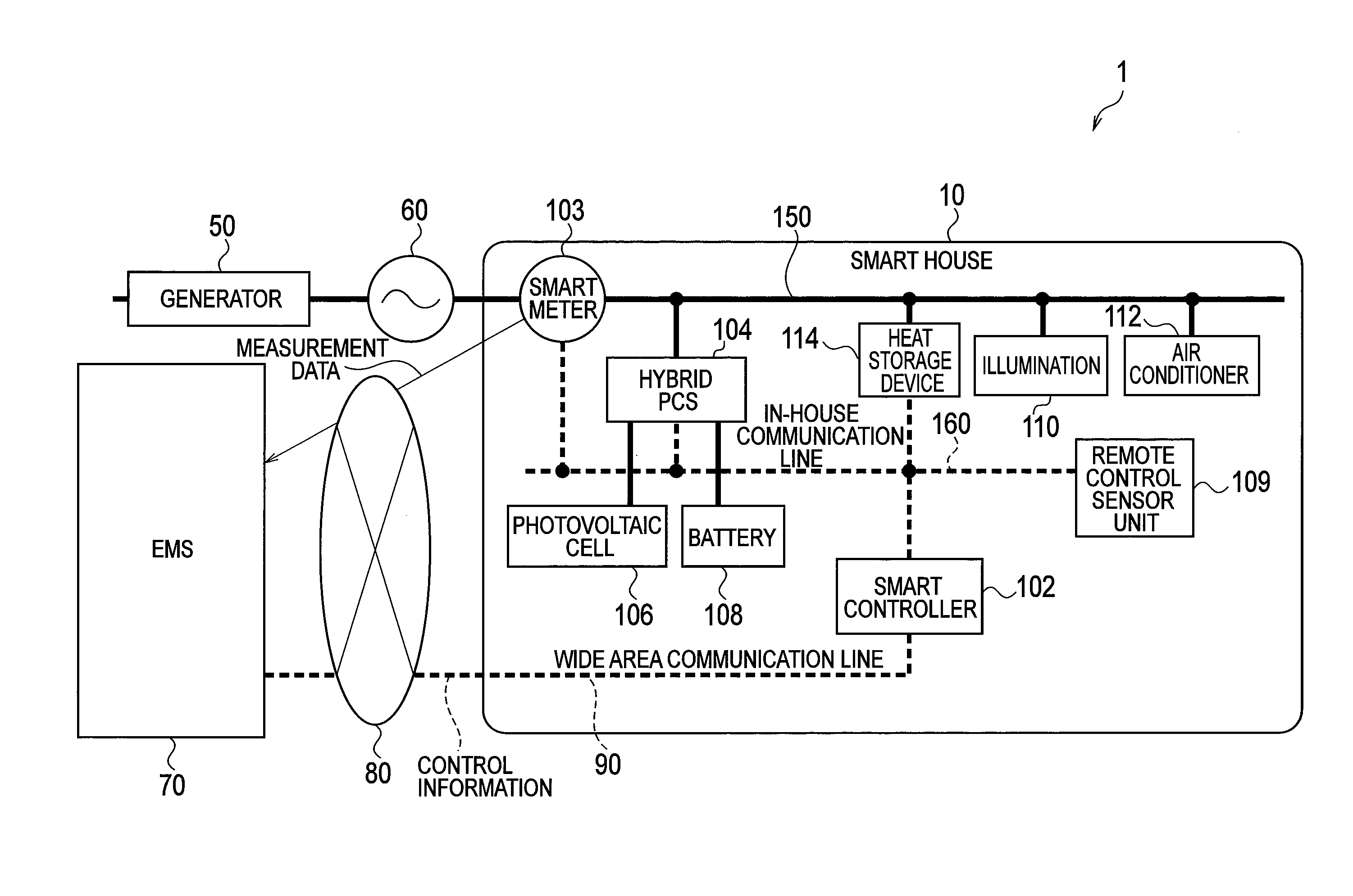
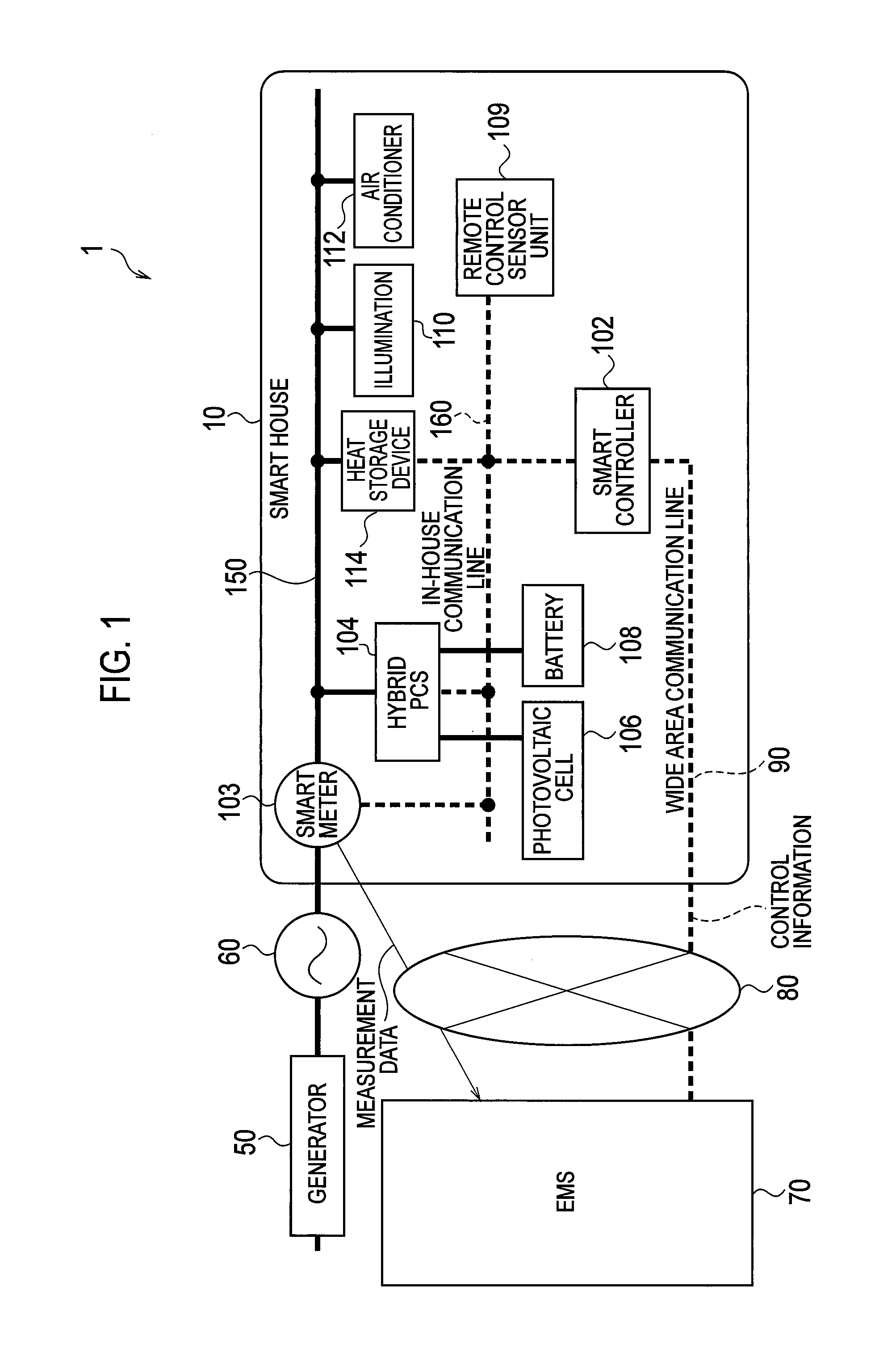
[0026]FIG. 1 is a configuration diagram of an electric power system 1 according to the embodiment of the present invention. The electric power system 1 illustrated in FIG. 1 is a system employing so-called a smart grid.

[0027]As illustrated in FIG. 1, the electric power system 1 includes a smart house 10 serving as a power consumer, a power generator 50 serving as a power supplier, an energy management system (EMS) 70 for controlling the whole power of the el...


PUM


Abstract

A smart controller (102) receives, from an EMS (70), control information as charge information that indicates electricity prices determined in accordance with a power supply of an electric power system (60) and an electric power demand of a consumer group. The smart controller (102) compares the electricity prices with a charge threshold value in a correspondence relationship between a predetermined operation mode and the charge threshold value, thereby determining the operation mode of an illumination (110), an air conditioning device (112), and a heat storage device (114) as loads so as to be an operation mode in which power consumption is reduced as the electricity prices becomes higher, and thus controlling the illumination (110), the air conditioning device (112), and the heat storage device (114) as the load.

Description

TECHNICAL FIELD[0001]The present invention relates to a control device provided in a power consumer including a DC power supply and loads, to control the loads, a control system provided with the control device and a device capable of operating a plurality of loads, and a control method in the control device.BACKGROUND ART[0002]In recent years, in view of the reduction of an environment load, in response to the generation of various factors, an electrical device that is a load suppresses its own power consumption. For example, when a temperature detected by a room temperature sensor is low, a refrigerator provided therein with the room temperature sensor suppresses power consumption by reducing the degree of cooling.[0003]Furthermore, there has been provided a system in which a DC power supply such as a photovoltaic cell is provided in a house and the like which are power consumers, electric power required by devices in the house is supplied by power generated by the DC power supply...

Claims


Application Information

Patent Timeline
IPC IPC(8): G06Q30/00G06Q50/00
CPCG06Q50/06H02J3/14H02J13/0062H02J2003/143H02J2003/146Y02B70/3225Y04S40/124Y04S20/224Y02B70/3266Y02B70/3275Y04S20/242Y04S20/244Y02B90/2638Y04S20/222H02J2310/64H02J2310/14H02J13/00016H02J13/00004Y02B70/30Y02B90/20Y04S50/10
Inventor KIUCHI, KAZUYAKUSAFUKA, KAORUWATANABE, TADAYUKISHICHIRI, KAZUMASAIWABUCHI, AKINORI
Owner KYOCERA CORP
Why Eureka
Try Eureka