Heater

Active Publication Date: 2012-09-27
NGK INSULATORS LTD
14 Cites 11 Cited by

AI-Extracted Technical Summary

Problems solved by technology

In the above conventional heaters, however, it has been difficult to rapidly raise a temperature of a lubricating fluid, while leaving, in an effective state, a mechanism which does not excessively heat the lubricating fluid.
In the inventions disclosed in Patent Documents 2 and 3, the heat...

Method used

[0034]Moreover, the heater of the present invention can continuously heat the lubricating fluid in the cells as described above. Therefore, the heater of the present invention can securely raise the temperature of the lubricating fluid, even when an amount of the heat to be generated per unit area of the partition walls is decreased. When the amount of the heat to be generated per unit area of the partition walls is decreased in this manner, it is possible to prevent the lubricating fluid from being excessively heated. Therefore, the heater of the present invention does not excessively heat the oil, but can rapidly raise the temperature of the lubricating fluid. Moreover, the heater of the present invention does not excessively heat the lubricating fluid as described above. Therefore, when the heater of the present invention is used, the deterioration of the lubricating fluid can be suppressed.
[0038]In the heater of the present invention, the honeycomb structure section preferably has a partition wall thickness of 0.1 to 0.51 mm, and a cell density of 15 to 280 cells/cm2. When the partition wall thickness and cell density of the honeycomb structure section are in the above ranges, it is possible to enhance an effect that the lubricating fluid is not excessively heated but the temperature of the lubricating fluid can rapidly be raised. Furthermore, the honeycomb structure section more preferably has “a partition wall thickness of 0.25 to 0.51 mm, and a cell density of 15 to 62 cells/cm2”, and further preferably has “a partition wall thickness of 0.30 to 0.38 mm, and a cell density of 23 to 54 cells/cm2”. This is because it is possible to decrease a pressure loss when the lubricating fluid flows through the honeycomb structure section.
[0042]The dense reaction-sintered SIC is prepared, for example, as follows. First, SiC powder and graphite powder are mixed and kneaded to prepare a kneaded material. Next, this kneaded material is formed to prepare a formed body. Next, this formed body is impregnated with “molten silicon (Si)”. In consequence, carbon constituting graphite is reacted with impregnated silicon to produce SiC. As described above, the formed body is “impregnated” with “molten silicon (Si)”, whereby pores easily disappear. That is, the pores are easily clogged. Therefore, it is possible to obtain a dense body. The “dense reaction-sintered SiC” is obtained in this manner.
[0045]When the partition walls contain the metal-impregnated SiC or metal-bonded SiC as a main component, an amount or type of the metal to be impregnated or bonded is adjusted, whereby the specific electrical resistance of the partition walls can be increased or decreased. When the partition walls contain the metal-impregnated SiC or the metal-bonded SiC as the main component, the specific electrical resistance of the partition walls usually becomes smaller as the amount of the metal to be impregnated or bonded.
[0050]Moreover, in the heater of the present invention, the amount of the heat to be generated per unit surface area of the partition walls depends on a size of the honeycomb structure section, the specific electrical resistance of each of the partition walls, the thickness of each partition wall, and the cell density. Therefore, in the heater of the present invention, when the size of the honeycomb structure section is predetermined in accordance with a breadth of a space where the heater is disposed, the thickness of the partition wall, the cell density or the specific electrical resistance of the partition wall is regulated, so that the amount of the heat to be generated per unit surface area of the partition walls can suitably be suppressed. In consequence, the lubricating fluid can be prevented from being excessively heated. The “size of the honeycomb structure section” is a length or a width of the honeycomb structure section.
[0051]Usually in the heater of the present invention, when the length of the honeycomb structure section (the lengths of the cells) is increased, the lubricating fluid can sufficiently be heated even in a case where the specific electrical resistances of the partition walls are decreased. In consequence, it is possible to rapidly raise the temperature of the lubricating fluid. Moreover, even when the length of the honeycomb structure section (the lengths of the cells) is small, the number of the cells is increased (e.g., the cell density is increased), the lubricating fluid can sufficiently be heated. Consequently, it is possible to rapidly raise the temperature of the lubricating fluid. In the heater of the present invention, the specific electrical resistances of the partition walls are preferably from 0.01 to 50 Ω·cm. The specific electrical resistances of the partition w...

Benefits of technology

[0017]A heater of the present invention does not excessively heat a lubricating fluid, but can...

Abstract

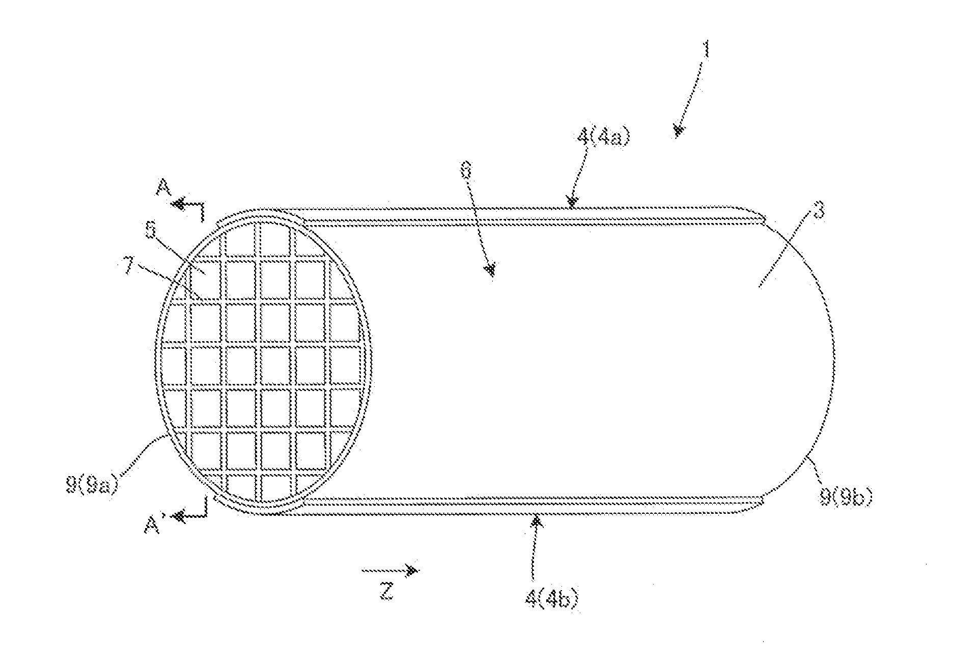
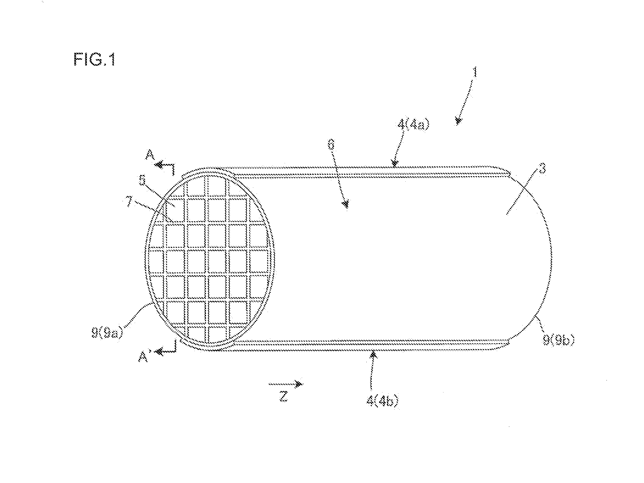
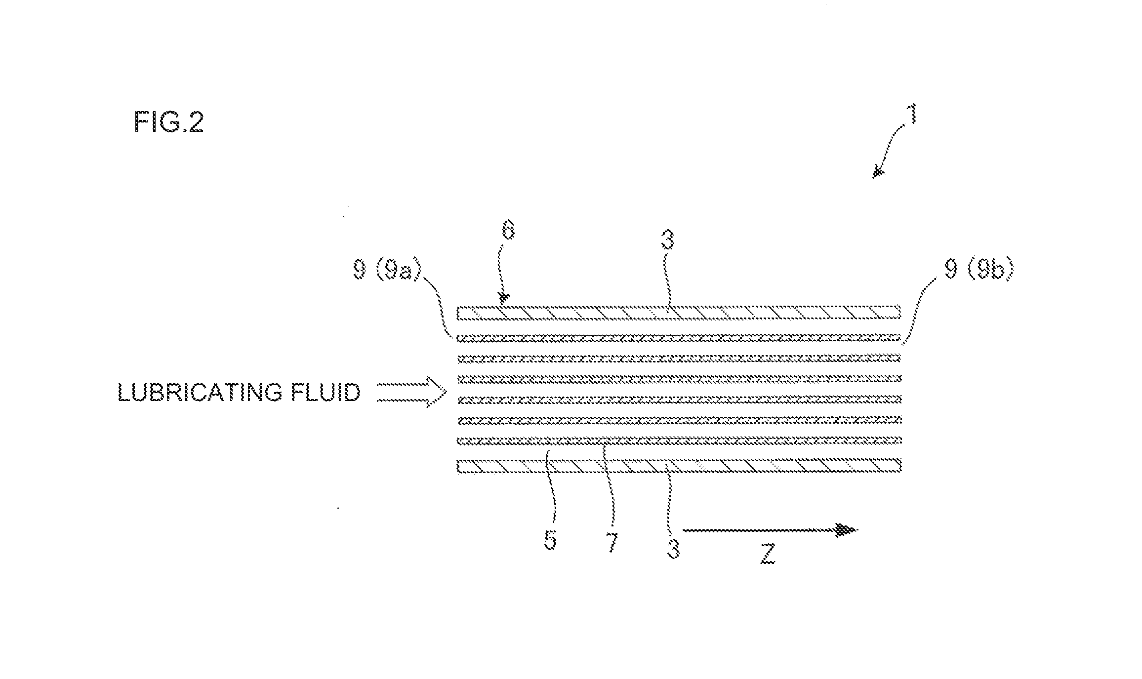
There is disclosed a heater which does not excessively heat a lubricating fluid but can rapidly raise a temperature of the lubricating fluid, even when a size thereof is small. A heater 1 includes a honeycomb structure section 6 including partition walls 7 which contain a ceramic as a main component and generate heat by electrical conduction, and a plurality of cells 5 which are partitioned and formed by the partition walls 7 and extend through the honeycomb structure section from one end 9a to another end 9b to become through channels of a lubricating fluid; and a pair of electrodes 4 which become an anode 4a and a cathode 4b to come in contact with the honeycomb structure section 6, thereby conducting the electricity through the partition walls 7 of the honeycomb structure section 6.

Application Domain

Ohmic-resistance electrodesHeater elements +4

Technology Topic

Image

  • Heater
  • Heater
  • Heater

Examples

  • Experimental program(11)

Example

Example 1
[0112]First, a honeycomb structure section content Si-bonded SiC as a main component was prepared. Specifically, SiC powder, metal Si powder, water and an organic binder were mixed and kneaded to prepare a kneaded material. Next, this kneaded material was formed in a honeycomb shape to prepare a honeycomb formed body. Next, the obtained honeycomb formed body was sintered in an inert gas atmosphere, to prepare the honeycomb structure section containing Si-bonded SiC as the main component.
[0113]Next, the side surface of the honeycomb structure section was coated with a silver (Ag) paste as an electrode forming raw material. Two portions of the side surface of the honeycomb structure section were coated with the electrode forming raw material. A shape of each coating film was a rectangular shape (a strip-like shape). Then, in a cross section orthogonal to an extending direction of cells, one of the two “coating films by the electrode forming raw material” was disposed on a side opposite to the other film via the center of a honeycomb formed body. Afterward, the body was degreased and sintered in an atmospheric furnace, to prepare a heater including the honeycomb structure section and a pair of electrodes. The Ag paste was a pasted material made of 40 to 95 mass % of silver.
[0114]A porosity of partition walls of the honeycomb structure section in the prepared heater was 40%. A cell shape of the honeycomb structure section was quadrangular. The cell shape of the honeycomb structure section is the cell shape in “the cross section orthogonal to the cell extending direction” of the honeycomb structure section. A specific electrical resistance (room temperature) of the heater was 30 Ω·cm. A cell density of the honeycomb structure section was 31 cells/cm2. A partition wall thickness of the honeycomb structure section was 0.3 mm. A thickness of an outer peripheral wall of the honeycomb structure section was 0.5 mm. A shape of an end surface of the honeycomb structure section (the cross section orthogonal to the cell extending direction) was a square, and a length of one side of the square (the length of the side of the cross section) was 40 mm. A length of the honeycomb structure section in the cell extending direction (the length of the honeycomb structure section) was 50 mm. A volume of the honeycomb structure section was 80 cm3. An electrical resistance of the heater was 37 Ω.
[0115]The obtained heater was subjected to “an electrical conduction test” by the following method.
[0116](Electrical Conduction Test)
[0117]On the surface of the electrode of the prepared heater, a pure aluminum (Al) plate (a plate thickness of 0.5 mm) whose shape is easily deformed is disposed, and on the surface of the pure aluminum plate, a power conducting power source-side connecting portion (an electrode) is disposed. That is, the pure aluminum plate is sandwiched between the electrode of the heater and the power conducting power source-side connecting portion (the electrode). Next, the electrode of the heater is mechanically (by bolt fastening) connected to the power conducting power source-side connecting portion (the electrode). Next, a predetermined voltage is applied to this heater, and an output (kW) obtained when the predetermined voltage is applied is confirmed.
[0118]In Example 1, when a voltage of 300.0 V was applied, an output of 2.4 kW was obtained. In the column of “output (kW)” of Table 1, the result of “electrical conduction test” is shown.
TABLE 1 Length Length of Volume of of one honey- honey- Specific Cell Partition side of comb comb Po- electrical density wall cross structure structure Resist- rosity resistance (cells/ thickness section section section ance Voltage Output Material (%) Cell shape (Ω· cm) cm2) (mm) (mm) (mm) (cm3) (Ω) (V) (kW) Example 1 Si-bonded SiC 40 Quadrangular 30 31 0.3 40 50 80 37 300.0 2.4 Example 2 Si-bonded SiC 40 Quadrangular 30 31 0.3 50 30 75 63 300.0 1.4 Example 3 Si-bonded SiC 40 Quadrangular 30 47 0.3 40 50 80 31 300.0 2.9 Example 4 Si-bonded SiC 40 Quadrangular 30 47 0.3 50 30 75 51 300.0 1.8 Example 5 Si-bonded SiC 40 Quadrangular 30 93 0.1 40 50 80 66 300.0 1.4 Example 6 Si-bonded SiC 40 Quadrangular 30 93 0.1 50 30 75 110 300.0 0.8 Example 7 Si-bonded SiC 40 Quadrangular 0.5 31 0.3 40 50 80 0.62 40.0 2.6 Example 8 Si-bonded SiC 40 Quadrangular 0.5 31 0.3 50 30 75 1.0 40.0 1.5 Example 9 Si-bonded SiC 40 Quadrangular 0.5 47 0.3 40 50 80 0.51 40.0 3.1 Example 10 Si-bonded SiC 40 Quadrangular 0.5 47 0.3 50 30 75 0.86 40.0 1.9 Example 11 Si-bonded SiC 40 Quadrangular 0.5 93 0.1 40 50 80 1.1 40.0 1.5 Example 12 Si-bonded SiC 40 Quadrangular 0.5 93 0.1 50 30 75 1.8 40.0 0.9 Example 13 Si-impregnated 0 Quadrangular 0.05 31 0.3 40 50 80 0.06 15.0 3.6 SiC Example 14 Si-impregnated 0 Quadrangular 0.05 31 0.3 50 30 75 0.10 15.0 2.2 SiC Example 15 Si-impregnated 0 Quadrangular 0.05 47 0.3 40 50 80 0.05 15.0 4.4 SiC Example 16 Si-impregnated 0 Quadrangular 0.05 47 0.3 50 30 75 0.09 15.0 2.6 SiC Example 17 Si-impregnated 0 Quadrangular 0.05 93 0.1 40 50 80 0.11 15.0 2.1 SiC Example 18 Si-impregnated 0 Quadrangular 0.05 93 0.1 50 30 75 0.18 15.0 1.2 SiC Example 19 Recrystallized 40 Quadrangular 1 31 0.3 40 50 80 1.2 60.0 2.9 SiC Example 20 Recrystallized 40 Quadrangular 1 31 0.3 50 30 75 2.1 60.0 1.7 SiC Example 21 Recrystallized 40 Quadrangular 1 47 0.3 40 50 80 1.0 60.0 3.5 SiC Example 22 Recrystallized 40 Quadrangular 1 47 0.3 50 30 75 1.7 60.0 2.1 SiC Example 23 Recrystallized 40 Quadrangular 1 93 0.1 40 50 80 2.2 60.0 1.6 SiC Example 24 Recrystallized 40 Quadrangular 1 93 0.1 50 30 75 3.7 60.0 1.0 SiC Example 25 Recrystallized 40 Quadrangular 0.5 31 0.3 40 50 80 0.6 40.0 2.6 SiC Example 26 Recrystallized 40 Quadrangular 0.5 31 0.3 50 30 75 1.0 40.0 1.5 SiC Example 27 Recrystallized 40 Quadrangular 0.5 47 0.3 40 50 80 0.5 40.0 3.1 SiC Example 28 Recrystallized 40 Quadrangular 0.5 47 0.3 50 30 75 0.9 40.0 1.9 SiC Example 29 Recrystallized 40 Quadrangular 0.5 93 0.1 40 50 80 1.1 40.0 1.5 SiC Example 30 Recrystallized 40 Quadrangular 0.5 93 0.1 50 30 75 1.8 40.0 0.9 SiC Example 31 Recrystallized 40 Quadrangular 0.1 31 0.3 40 50 80 0.12 20.0 3.2 SiC Example 32 Recrystallized 40 Quadrangular 0.1 31 0.3 50 30 75 0.21 20.0 1.9 SiC Example 33 Recrystallized 40 Quadrangular 0.1 47 0.3 40 50 80 0.10 20.0 3.9 SiC Example 34 Recrystallized 40 Quadrangular 0.1 47 0.3 50 30 75 0.17 20.0 2.3 SiC Example 35 Recrystallized 40 Quadrangular 0.1 93 0.1 40 50 80 0.22 20.0 1.8 SiC Example 36 Recrystallized 40 Quadrangular 0.1 93 0.1 50 30 75 0.37 20.0 1.1 SiC Example 37 Reaction- 40 Quadrangular 1 31 0.3 40 50 80 1.24 60.0 2.9 sintered SiC (porous) Example 38 Reaction- 40 Quadrangular 1 31 0.3 50 30 75 2.09 60.0 1.7 sintered SiC (porous) Example 39 Reaction 40 Quadrangular 1 47 0.3 40 50 80 1.02 60.0 3.5 sintered SiC (porous) Example 40 Reaction- 40 Quadrangular 1 47 0.3 50 30 75 1.71 60.0 2.1 sintered SiC (porous)
TABLE 2 Length Length of Volume of of one honey- honey- Specific Cell Partition side of comb comb Po- electrical density wall cross structure structure Resist- Out- rosity resistance (cells/ thickness section section section ance Voltage put Material (%) Cell shape (Ω· cm) cm2) (mm) (mm) (mm) (cm3) (Ω) (V) (kW) Example 41 Reaction- 40 Quadrangular 1 93 0.1 40 50 80 2.19 60.0 1.6 sintered SiC (porous) Example 42 Reaction- 40 Quadrangular 1 93 0.1 50 30 75 0.37 20.0 1.1 sintered SiC (porous) Example 43 Reaction- 0 Quadrangular 0.05 31 0.3 40 50 80 0.06 15.0 3.6 sintered SiC (dense) Example 44 Reaction- 0 Quadrangular 0.05 31 0.3 50 30 75 0.10 15.0 2.2 sintered SiC (dense) Example 45 Reaction- 0 Quadrangular 0.05 47 0.3 40 50 80 0.05 15.0 4.4 sintered SiC (dense) Example 46 Reaction- 0 Quadrangular 0.05 47 0.3 50 30 75 0.09 15.0 2.6 sintered SiC (dense) Example 47 Reaction- 0 Quadrangular 0.05 93 0.1 40 50 80 0.11 15.0 2.1 sintered SiC (dense) Example 48 Reaction- 0 Quadrangular 0.05 93 0.1 50 30 75 0.18 15.0 1.2 sintered SiC (dense) Example 49 Reaction- 0 Quadrangular 0.01 31 0.3 40 50 80 0.01 5.0 2.0 sintered SiC (dense) Example 50 Reaction- 0 Quadrangular 0.01 31 0.3 50 30 75 0.02 5.0 1.2 sintered SiC (dense) Example 51 Reaction- 0 Quadrangular 0.01 47 0.3 40 50 80 0.01 5.0 2.4 sintered SiC (dense) Example 52 Reaction- 0 Quadrangular 0.01 47 0.3 50 30 75 0.02 5.0 1.5 sintered SiC (dense) Example 53 Reaction- 0 Quadrangular 0.01 93 0.1 40 50 80 0.02 5.0 1.1 sintered SiC (dense) Example 54 Reaction- 0 Quadrangular 0.01 93 0.1 50 30 75 0.04 5.0 0.7 sintered SiC (dense) Example 55 Si-bonded SiC 40 Hexagonal 30 47 0.3 40 50 80 16 200.0 2.5 Example 56 Si-bonded SiC 40 Hexagonal 30 47 0.3 50 30 75 28 200.0 1.4 Example 57 Si-bonded SiC 40 Hexagonal 0.5 47 0.3 40 50 80 0.26 40.0 6.1 Example 58 Si-bonded SiC 40 Hexagonal 0.5 47 0.3 50 30 75 0.46 40.0 3.5 Example 59 Si-impregnated 0 Hexagonal 0.05 47 0.3 40 50 80 0.03 10.0 3.8 SiC Example 60 Si-impregnated 0 Hexagonal 0.05 47 0.3 50 30 75 0.05 10.0 2.2 SiC Example 61 Recrystallized 40 Hexagonal 1 47 0.3 40 50 80 0.52 40.0 3.1 SiC Example 62 Recrystallized 40 Hexagonal 1 47 0.3 50 30 75 0.92 40.0 1.7 SiC Example 63 Recrystallized 40 Hexagonal 0.5 47 0.3 40 50 80 0.26 20.0 1.5 SiC Example 64 Recrystallized 40 Hexagonal 0.5 47 0.3 50 30 75 0.46 20.0 0.9 SiC Example 65 Recrystallized 40 Hexagonal 0.1 47 0.3 40 50 80 0.05 15.0 4.3 SiC Example 66 Recrystallized 40 Hexagonal 0.1 47 0.3 50 30 75 0.09 15.0 2.4 SiC Example 67 Reaction- 40 Hexagonal 1 47 0.3 40 50 80 0.52 15.0 0.4 sintered SiC (porous) Example 68 Reaction- 40 Hexagonal 1 47 0.3 50 30 75 0.92 15.0 0.2 sintered SiC (porous) Example 69 Reaction- 0 Hexagonal 0.05 47 0.3 40 50 80 0.03 10.0 3.8 sintered SiC (dense) Example 70 Reaction- 0 Hexagonal 0.05 47 0.3 50 30 75 0.05 10.0 2.2 sintered SiC (dense) Example 71 Reaction- 0 Hexagonal 0.01 47 0.3 40 50 80 0.01 5.0 4.8 sintered SiC (dense) Example 72 Reaction- 0 Hexagonal 0.01 47 0.3 50 30 75 0.01 5.0 2.7 sintered SiC (dense) Example 73 BaTiO3 — Quadrangular 100 47 0.3 40 50 80 102 500.0 2.7 Example 74 V2O3 — Quadrangular 0.001 47 0.3 40 50 80 0.0011 2.0 4.3

Example

Examples 2 to 12 and 55 to 58
[0119]Heaters were prepared in the same manner as in Example 1 except that conditions of a honeycomb shape were changed as shown in Table 1 and materials for use were changed as follows. The prepared heaters were subjected to “an electrical conduction test” in the same manner as in Example 1. The results are shown in Tables 1 and 2.

Example

Examples 13 to 18, 59 and 60
[0120]First, a honeycomb structure section containing Si-impregnated SiC as a main component was prepared. Specifically, SiC powder, an organic binder and water were mixed and kneaded to prepare a kneaded material. Next, this kneaded material was formed in a predetermined honeycomb shape shown in Table 1 or 2 to prepare a formed body. Next, on the obtained formed body, a lump of metal Si was mounted, and impregnated with Si in a reduced pressure argon (Ar) gas. Thus, the honeycomb structure section containing Si-impregnated SiC as a main component was prepared. Next, a coating film was formed in the same manner as in Example 1, to form a pair of electrodes on the side surface of the honeycomb structure section. In this way, heaters each including the honeycomb structure section and the pair of electrodes were prepared.
[0121]Next, the prepared heaters were subjected to “an electrical conduction test” in the same manner as in Example 1. The results are shown in Tables 1 and 2.

PUM

no PUM

Description & Claims & Application Information

We can also present the details of the Description, Claims and Application information to help users get a comprehensive understanding of the technical details of the patent, such as background art, summary of invention, brief description of drawings, description of embodiments, and other original content. On the other hand, users can also determine the specific scope of protection of the technology through the list of claims; as well as understand the changes in the life cycle of the technology with the presentation of the patent timeline. Login to view more.

Similar technology patents

Method of producing resin varnish for printing ink

ActiveUS6894096B2Easily produceRaise temperatureInksNatural resin chemical modificationSolventChemistry
Owner:HARIMA CHEM INC

Geothermal district heating power system

PendingUS20220259989A1Raise temperatureDistrict heating systemLighting and heating apparatusFossil fuelHeating power
Owner:ORMAT TECH INC

Classification and recommendation of technical efficacy words

Why Eureka
Try Eureka