Motor Yaw Drive System for a Wind Turbine

a technology of yaw motor and wind turbine, which is applied in the direction of machines/engines, mechanical equipment, electric generator control, etc., can solve the problems of multiple motor drives sharing power, wind turbine yaw error, and lower amount of wind energy impinging on the rotor area, so as to reduce the lifetime cost of ownership and reduce the cost of yaw motor

Inactive Publication Date: 2012-09-27
CLIPPER WINDPOWER INC
View PDF2 Cites 11 Cited by
  • Summary
  • Abstract
  • Description
  • Claims
  • Application Information

AI Technical Summary

Benefits of technology

[0014]It is a further advantage of the invention to provide a wind turbine which has reduced Lifetime Cost of Ownership.
[0015]It is a further advantage of the invention that the yaw-drive system provides proportional control on the yaw motor and brake system to significantly reduce the cost of the yaw motor.

Problems solved by technology

The wind turbine has a yaw error if the rotor is not aligned with the wind.
A yaw error will result in a lower amount of the wind energy impinging upon the rotor area.
These systems encounter problems such as frozen motor shafts, multiple motor drives sharing power, complexity and low reliability due to the large amount of moving parts.

Method used


Image

  • Motor Yaw Drive System for a Wind Turbine
  • Motor Yaw Drive System for a Wind Turbine
  • Motor Yaw Drive System for a Wind Turbine

Examples


second embodiment

[0049]Refer to FIG. 3B, which is a cross-sectional view of the invention along the view lines 3-3 of FIG. 2.

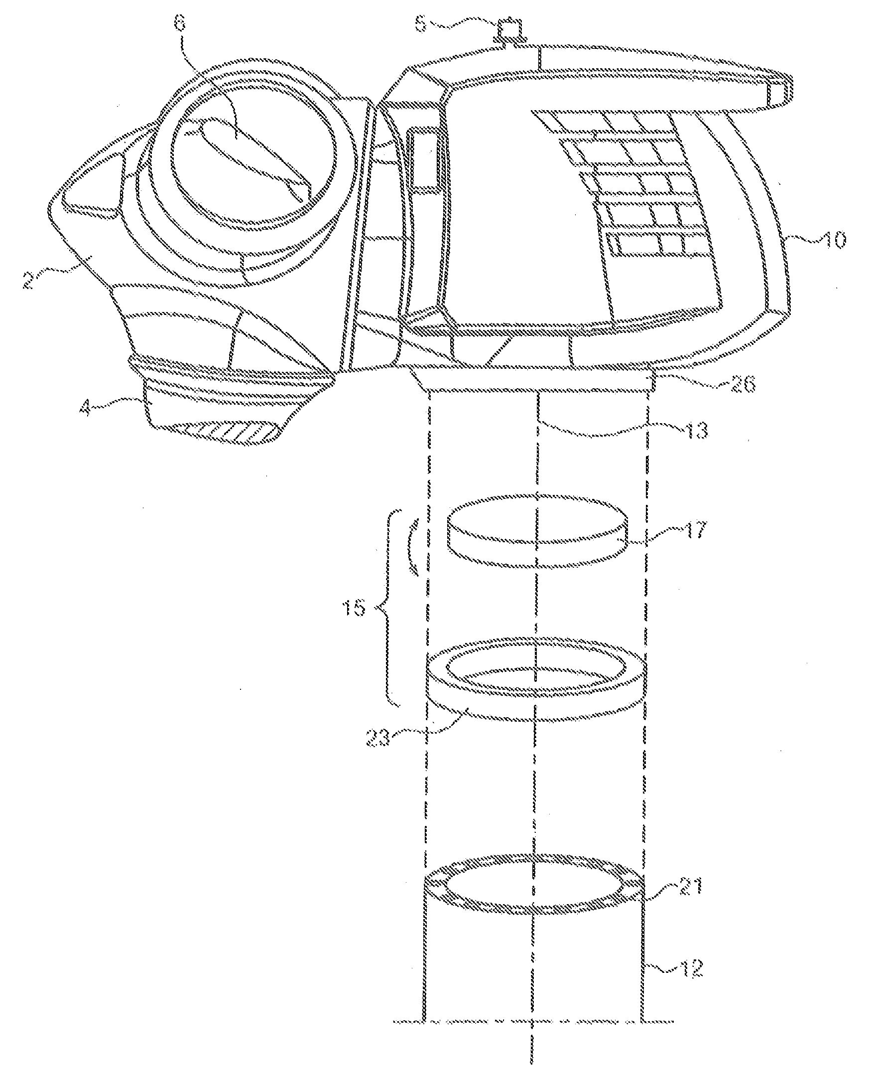
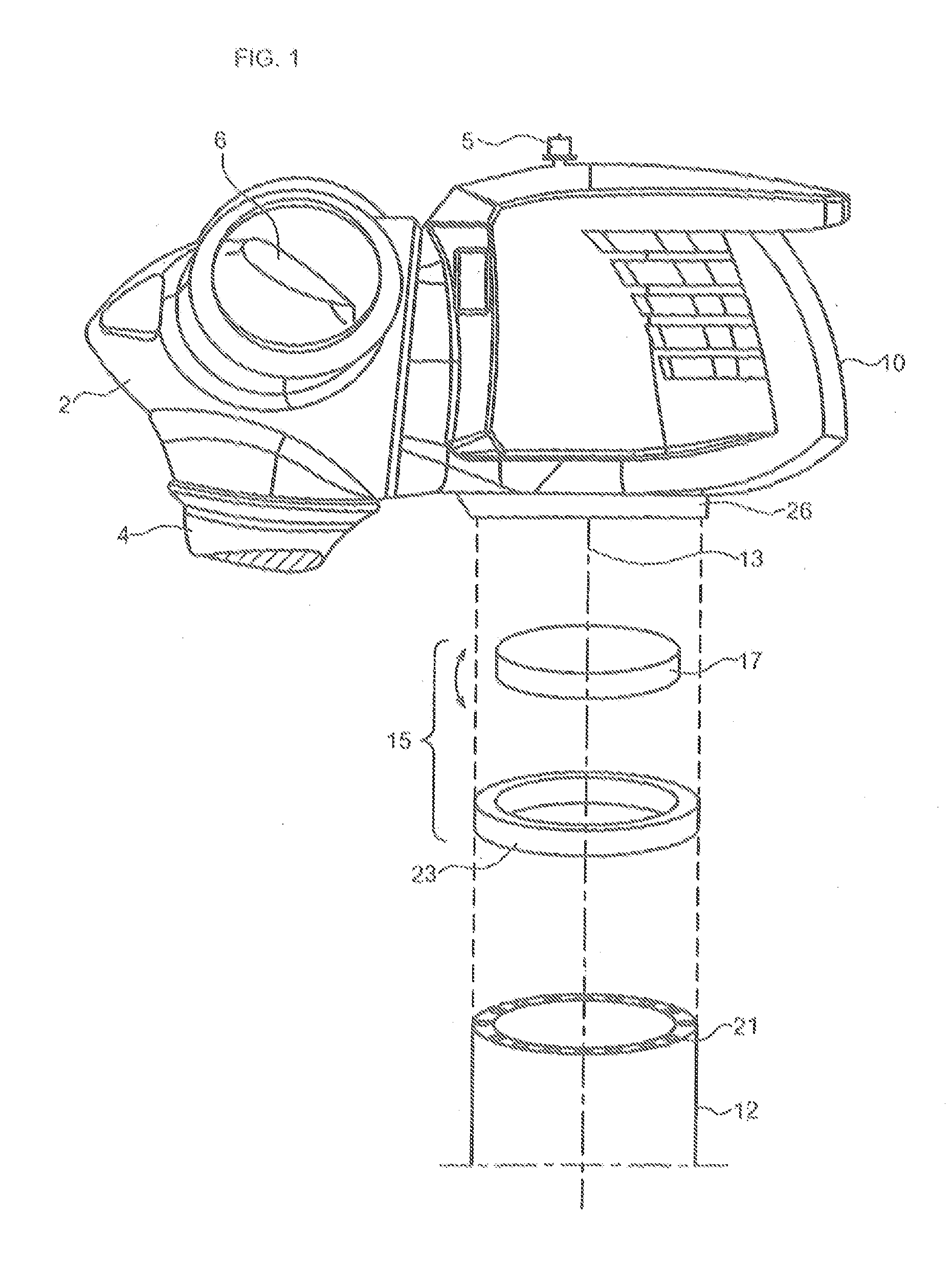
[0050]A round-loop high-flux core material 23 forms the stator of the circular linear yaw motor. The permanent magnets 14, 18 are part of the circular linear yaw motor upon which the top part (nacelle) of the wind turbine rotates. The permanent magnets 14, 18 are within U-shaped circular motor rotor 17, which is bolted to the tower 12. The cable tray 19 of the first embodiment shown in FIG. 3A that contains the start and finish connections is eliminated as unnecessary in this second embodiment.

[0051]The yaw motor electronic quadrature drive circuitry 39 is located in the nacelle and is connected to two pairs of wires 20. One pair of wires is connected to the stator pole coils, which are wound around each pole counterclockwise to drive the motor rotor first direction. The other pair of wires is connected to the stator pole coils and are wound around each pole clockwise to drive...

first embodiment

[0057]Refer to FIG. 3C, which is a detail view of the invention shown in FIG. 3A. A round-loop high-flux core material 16 forms the stator of the circular linear yaw motor, which is bolted to the nacelle. Permanent magnets 14, 18 are part of the circular linear yaw motor upon which the top part (nacelle) of the wind turbine rotates. The permanent magnets 14, 18 are within an inverted U-shaped circular motor rotor 17, which is bolted to the nacelle. The horizontal orientation of the core windings is such that the flux path is perpendicular to the air gap between the core and the permanent magnets 14, 18.

[0058]FIG. to 3D, which is a detail view of the second embodiment of the invention shown in FIG. 3B; A round-loop high-flux core material 16 forms the stator of the circular linear yaw motor, which is bolted to the nacelle. Permanent magnets 14, 18 are part of the circular linear yaw motor upon which the top part (nacelle) of the wind turbine rotates. The permanent magnets 14, 18 are ...


PUM


Abstract

A yaw-drive system for a wind turbine housed in a movable-in-yaw nacelle affixed atop a tower on a roller bearing. A round-look high-flux core material forms the stator of a circular linear yaw motor. The stator is affixed to the tower and is stationary. A plurality of magnets is affixed to the nacelle in proximity with the core material, such that as the stator is excited in quadrature the nacelle rotates on the roller bearings about a yaw pivot.

Description

BACKGROUND OF THE INVENTION[0001]1. Field of the Invention[0002]This invention relates to wind turbines and more particularly to wind turbines mounted on a support structure for motion about a yaw axis.[0003]2. Description of the Prior Art[0004]A wind turbine employs wind turbine electric-power generator units, which utilize the rotation force generated by wind force on a plurality of rotor blades. The blades drive generator units via a rotor shaft and gears. The generator units are controlled by adjusting the pitch angle of the rotor blades to keep generation of power corresponding with the energy of wind and the required generation power at the time of operation.[0005]The generator units are enclosed within a nacelle, along with a transmission mechanism for transmitting the rotation of the main shaft to the generator units, and are supported for rotation in a horizontal plane on a tower.[0006]To ensure that the horizontal-axis wind turbine is producing a maximum amount of electric...

Claims


Application Information

Patent Timeline
Patent Type & Authority Applications(United States)
IPC IPC(8): H02P9/04
CPCF03D7/0204H02K7/14H02K7/1838Y02E10/723Y02E10/725H02K41/031Y02E10/72
Inventor GARFINKEL, MARKCOUSINEAU, KEVIN L.WAHL, PETERSTEEN, STEPHEN
Owner CLIPPER WINDPOWER INC
Why Eureka
Try Eureka