Printing apparatus, printing method, printing data generation program, and dither mask generation method

a printing apparatus and mask technology, applied in the field of printing apparatus, can solve the problems of paper feeding accuracy, deterioration of printing quality, and deterioration of operation accuracy of printing head, and achieve the effect of suppressing variations in printing image quality, favorable blue noise characteristic, and suppressing the variation of dot covering ratio

Active Publication Date: 2012-09-27
SEIKO EPSON CORP
View PDF16 Cites 11 Cited by
  • Summary
  • Abstract
  • Description
  • Claims
  • Application Information

AI Technical Summary

Benefits of technology

[0113]The printer 20 with this configuration performs printing according to dot data generated by the dither mask 62 where threshold values corresponding to a part of groups of the outward movement pixel groups and the inward movement pixel groups are shifted by predetermined pixels in a predetermined direction with respect to the threshold value disposition of the dither mask 61 which is set to have the noise characteristics having a peak on the high frequency side. For this reason, in a case where a dot position shift between the pixel groups occurs, it is possible to suppress variations in the dot covering ratio due to a position shift direction or amount. As a result, it is possible to suppress printing image quality from being deteriorated due to occurrence of density unevenness in a printing image of the common region. In addition, the threshold value disposition of the dither mask 61 which is a base of the dither mask 62 has the noise characteristics having a peak on the high frequency side, and thus a printed image shows characteristics close to the so-called blue noise characteristic at least in the common region, thereby securing a predetermined extent of graininess.
[0114]FIG. 19 shows an example of the effect achieved by the printer 20. FIG. 19 shows a simulation result. Specifically, for a dot formation pattern using a dither mask showing a favorable blue noise characteristic, cases where various amounts of Bi-D shifts occur in the main scanning direction and the sub-scanning direction are set, and a covering ratio is obtained and is plotted for each case. The transverse axis of FIG. 9 expresses a sum value of position shift amounts in the main scanning direction and the sub-scanning direction (hereinafter, also referred to as a total shift amount). The pre-requisites of the simulation are as follows.
[0115]With respect to the position shift amount, seven types of shift amounts are set as a shift amount in the main scanning direction by employing 0 pixels and between 0.5 and 5.5 pixels with one pixel interval. In addition, as a shift amount in the sub-scanning direction, nine types of shift amounts are set by employing between 0 to 4 pixels with 0.5 pixel interval. In FIG. 19, covering ratios of the cases (51 types) where the total shift amount is less than 7 pixels among the cases of the Bi-D shift of all the combinations (63 types) of the shift amounts are plotted.
[0116]As shown in FIG. 19, upon comparison of the case where the total shift amount is 0 pixels and the case where it is 2 pixels, a difference of 10% or more occurs in the covering ratio. On the other hand, if the total shift amount becomes larger than 2 pixels, it can be seen that a variation amount of the covering ratio is decreased according to an increase in the total shift amount. Upon comparison of the case where the total shift amount is 2 pixels with the case where it is 3 pixels, a variation in the covering ratio is about 2%. In addition, if the total shift amount exceeds 5 pixels, a variation in the covering ratio is very stable, and thus the covering ratio is hardly varied even if the total shift amount is increased. This corresponds to the fact that the dot pair generation ratio K nearly converges on k2 if a threshold value shift amount is equal to or more than 5 pixels when the above-described dither mask 62 is generated.
[0117]Here, in a case where a threshold value shift amount when the dither mask 62 is generated is 5 pixels, if a position shift amount occurring in practice is ±2 pixels, a range of the substantial position shift amount shown in a printing image is a range of 3 pixels to 7 pixels. In this range, a variation width of the covering ratio is less than 2%. On the other hand, in a case where a threshold value shift amount when the dither mask 62 is generated is 0 pixels, that is, in a case of using the dither mask 61 in the related art having the blue noise characteristic, if a position shift amount occurring in practice is ±2 pixels, a range of the substantial position shift amount shown in a printing image is a range of −2 pixels to 2 pixels. In this range, a variation width of the covering ratio is equal to or more than 14%.
[0118]As is clear from the above description, the dither mask 62 can considerably suppress a variation in the covering ration. A local variation in the covering ratio means occurrence of density unevenness in a printing image. Therefore, if the variation in the covering ratio in the printing image is suppressed by the use of the dither mask 62, it is possible to considerably suppress the occurrence of density unevenness.

Problems solved by technology

Causes of the position shift may include a problem of operation accuracy of the printing head, a problem of paper feeding accuracy, and the like.
If this position shift fluctuation occurs, there are cases where local density unevenness is generated in a printing image, and thereby printing quality is deteriorated.
As a result, it is possible to suppress printing image quality from being suppressed due to occurrence of density unevenness in a printing image of the common region.

Method used


Image

  • Printing apparatus, printing method, printing data generation program, and dither mask generation method
  • Printing apparatus, printing method, printing data generation program, and dither mask generation method
  • Printing apparatus, printing method, printing data generation program, and dither mask generation method

Examples


modified example 1

B-1. Modified Example 1

[0122]In the above-described embodiment, in step S231, the pixel groups of a printing image are divided into a pixel group formed by the outward movement dots and a pixel group formed by the inward movement dot, and the dither mask 62 is generated by shifting threshold values corresponding to any one of the pixel groups by predetermined pixels in a predetermined direction with respect to the threshold value disposition of the dither mask 61. However, the divided pixel groups are not limited to the above-described example, and may be pixel groups having different printing conditions.

[0123]For example, in a case where an image of a predetermined region is printed through a plurality of main scannings of the printing head 90, pixel groups of the printing image may be divided into pixel groups where dots are formed by different main scannings of the plurality of main scannings. For example, the attention region shown in FIG. 3 is formed through repetition of regio...

modified example 2

B-2. Modified Example 2

[0124]Although the evaluation values E are calculated in the overall printing grayscale range and the threshold value disposition of the dither mask 61 is determined in the above-described embodiment, threshold value disposition may be determined based on evaluation values E in a part of the printing grayscale range. For example, in a high grayscale printing region where dot dispersibility is not greatly problematic, threshold value disposition of the dither mask 61 may be set by other methods.

modified example 3

B-3. Modified Example 3

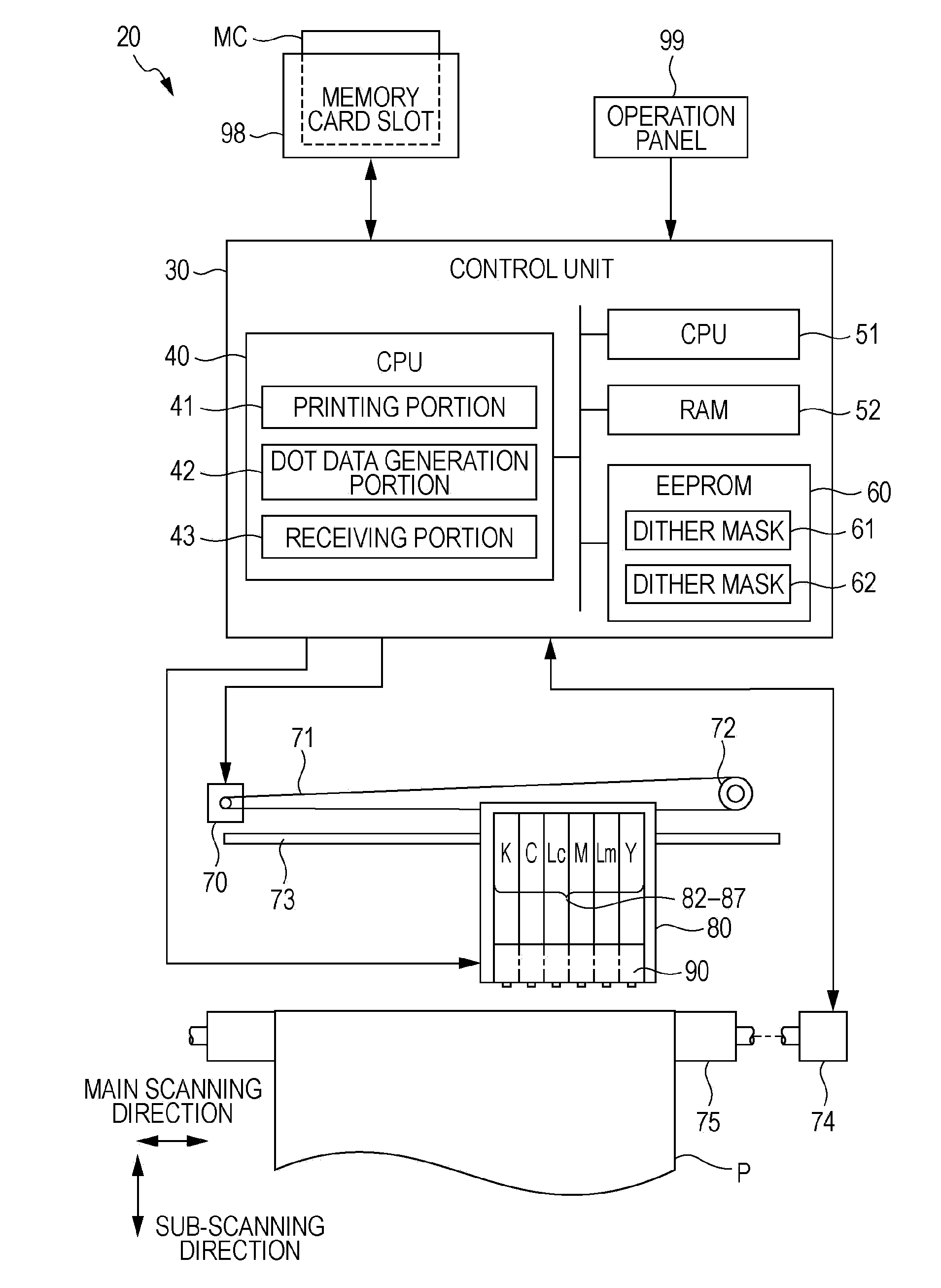
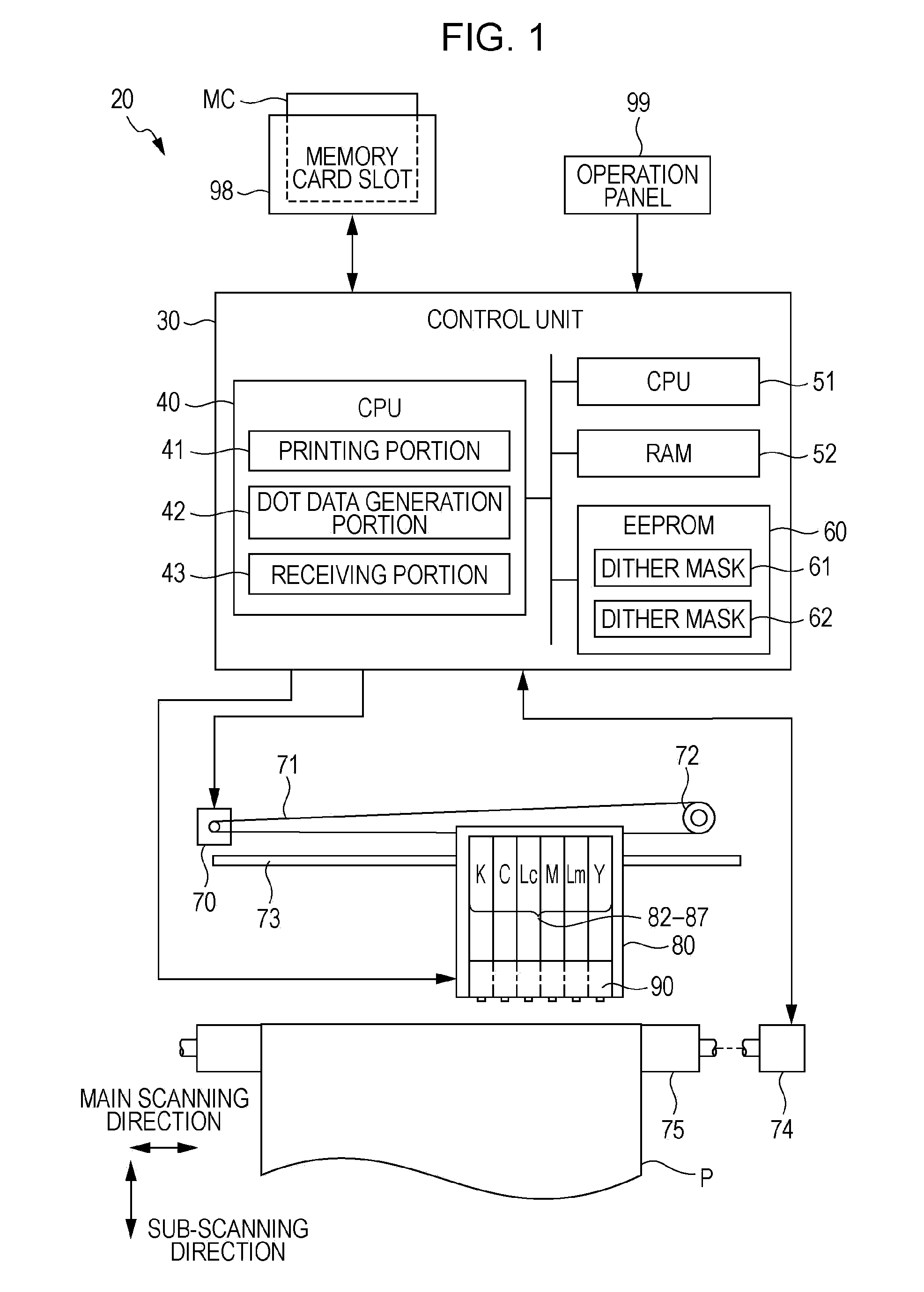
[0125]Although the dither mask 61 and the dither mask 62 are stored in the EEPROM 60 in advance in the above-described embodiment, the invention is not limited thereto. For example, either the dither mask 61 or the dither mask 62 may be stored in the EEPROM 60 in advance. In this case, the CPU 40 may function as a dither mask generation portion, and may generate the other dither mask from one of the dither mask 61 and the dither mask 62. Of course, in the halftone process, a dither mask is not necessarily selected depending on the kind of printing medium, but the printer 20 may store only the dither mask 62 and use the dither mask 62 in a fixed manner regardless of the kind of printing medium, or may change and use a dither mask different from the dither mask 61, and the dither mask 62.


PUM


Abstract

A printing apparatus which forms dots, according to dot data generated through comparison of a grayscale value of each of pixels with each of threshold values of a dither mask. The printing apparatus forms the dots through division into a plurality of pixel groups having different printing conditions and performs at least a part of the dot formation by the pixel groups in a common region. The dither mask has a second threshold value disposition, with respect to a first threshold value disposition which is each of dispositions of the respective threshold values set such that distribution of dots formed in the common region has noise characteristics having a peak on a high frequency side, in a case where a relative position of the dots between the pixel groups is formed in a target positional relationship which is a target in at least a part of a printing grayscale region.

Description

[0001]This application claims priority to Japanese Patent Application No. 2011-065689 filed on Mar. 24, 2011.BACKGROUND[0002]1. Technical Field[0003]The present invention relates to a printing apparatus which performs printing by ejecting ink on a printing medium from a printing head.[0004]2. Related Art[0005]In a serial ink jet type printer, a printing head having a plurality of nozzles is relatively moved in the main scanning direction and sub-scanning direction with respect to a printing medium, and ink is ejected from the nozzles so as to form dots on the printing medium, thereby performing printing. In such an ink jet type printer, there are cases where a position shift occurs in which a landing position of the ink ejected from the nozzle of the printing head to the printing medium is shifted from a target position. Causes of the position shift may include a problem of operation accuracy of the printing head, a problem of paper feeding accuracy, and the like. For example, if in...

Claims


Application Information

Patent Timeline
Patent Type & Authority Applications(United States)
IPC IPC(8): H04N1/405
CPCH04N1/4051H04N1/52H04N1/4058
Inventor KAKUTANI, TOSHIAKI
Owner SEIKO EPSON CORP
Why Eureka
Try Eureka