Pressure reducing valve having shutoff mechanism

a technology of pressure reducing valve and shutoff mechanism, which is applied in the direction of fluid pressure control, process and machine control, instruments, etc., can solve the problems of increasing the size or cost of a product, and achieve the effect of preventing degradation of the contact surface, reducing the minimum closing load of the valve body, and reducing the size or cost of the produ

Inactive Publication Date: 2012-10-04
HONDA MOTOR CO LTD
View PDF13 Cites 6 Cited by
  • Summary
  • Abstract
  • Description
  • Claims
  • Application Information

AI Technical Summary

Benefits of technology

[0019]According to the aspect (A), the area of the pressure receiving surface of the diaphragm and the spring constant of the spring are set so as to satisfy the equations (1) and (2), and the valve body is closed in the range where the pressure in the secondary pressure chamber acting on the diaphragm as the thrust force in the valve closing direction does not exceed the allowable maximum pressure of the pressure receiving device. Accordingly, it is possible to prevent the high-pressure fluid from excessively leaking to the pressure receiving device without further providing a valve mechanism dedicated for a stop valve. Thus, according the invention, it is possible to suppress an increase in size or cost of the product.
[0020]According to the aspect (B), the valve body and the valve seat come into contact with each other at the conical first contact surface and the annular second contact surface having the circular-arc cross-section portion. Then, one of the contact surfaces...

Problems solved by technology

However, in the pressure reducing valve of the related art since plural types of valve mechanisms are assembled inside the ...

Method used


Image

  • Pressure reducing valve having shutoff mechanism
  • Pressure reducing valve having shutoff mechanism
  • Pressure reducing valve having shutoff mechanism

Examples


Embodiment Construction

[0031]Hereinafter, an exemplary embodiment of the invention will be described by referring to the drawings.

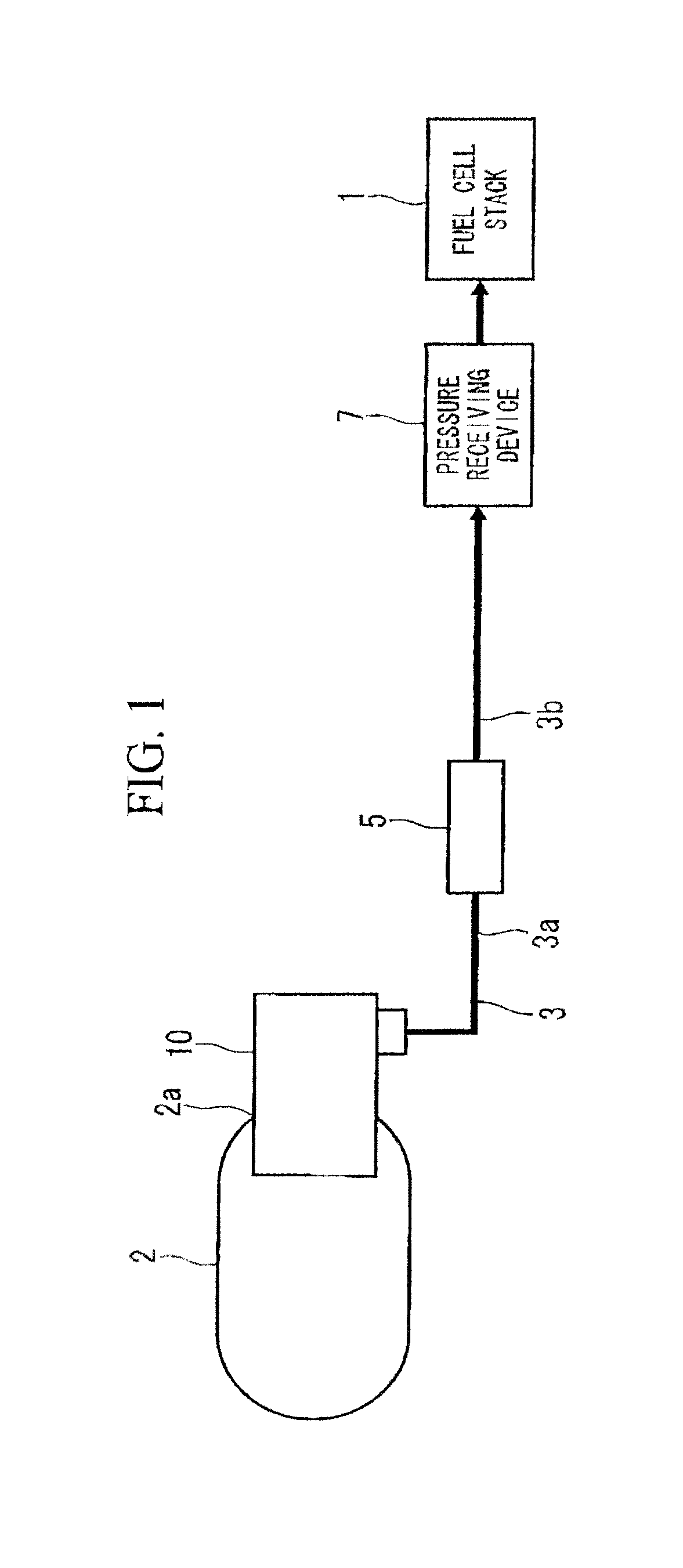
[0032]FIG. 1 is a schematic configuration diagram illustrating a fuel cell system, where reference numeral 1 denotes a fuel cell stack (a fuel cell) which generates electric power by receiving hydrogen as fuel and oxygen as an oxidizing agent. The fuel cell stack 1 is, for example, a polymer electrode fuel cell (PEFC), and is formed by stacking plural cells each of which is formed by sandwiching a membrane electrode assembly (MEA) using separators (not shown).

[0033]A hydrogen gas of a predetermined pressure and a predetermined flow rate is supplied from a hydrogen tank 2 (a high-pressure fluid supply source) storing high-pressure hydrogen to the fuel cell stack 1 through a hydrogen supply passageway 3, and air of a predetermined pressure and a predetermined flow rate is supplied to the fuel cell stack 1 through an air supply device (not shown).

[0034]The hydrogen tank 2 is forme...


PUM


Abstract

A high-pressure side primary pressure chamber communicates with a secondary pressure chamber on the side of a pressure receiving device through a communication hole. A diaphragm which receives the pressure in the secondary pressure chamber is provided, and a valve body is connected to the diaphragm. The diaphragm is biased by a spring in a valve opening direction. The area S (mm2) of the pressure receiving surface of the diaphragm and the spring constant k (N/mm) of the spring are set so as to satisfy the following equations (1) and (2).
PS−k×ΔL>C  (1)
P1<P2  (2)
    • where P1 denotes the pressure (MPa or N/mm2) of the secondary pressure chamber, ΔL denotes the displacement (mm) of the spring, C denotes the minimum closing load (N) of the valve body, and P2 denotes the allowable maximum pressure (MPa or N/mm2) of the pressure receiving device.

Description

CROSS-REFERENCE TO RELATED APPLICATION[0001]Priority is claimed on Japanese Patent Application No. 2011-074824, filed Mar. 30, 2011, the disclosure of which is hereby incorporated herein by reference in its entirety.BACKGROUND OF THE INVENTION[0002]1. Field of the Invention[0003]The present invention relates to a pressure reducing valve which depressurizes a supply source side high-pressure fluid into a predetermined pressure and supplies the result to a low-pressure passageway provided with a pressure receiving device, and particularly, to a pressure reducing valve having a shutoff mechanism which has a function of preventing a high-pressure fluid of a low-pressure passageway from leaking to a supply source when a pressure receiving device stops.[0004]2. Description of Related Art[0005]In a fuel cell, a hydrogen tank filled with high-pressure hydrogen may be used as an anode-side fluid supply source. In a system which handles a high-pressure fluid, a pressure reducing valve is inst...

Claims


Application Information

Patent Timeline
IPC IPC(8): G05D16/06F16K1/38
CPCG05D16/0655G05D16/0658Y10T137/782
Inventor MIURA, TANEAKIOZAKI, HIROYASUTAKAKU, KOICHIKATO, KOICHI
Owner HONDA MOTOR CO LTD
Why Eureka
Try Eureka