In-wheel motor drive device

Active Publication Date: 2012-10-04
AISIN AW CO LTD
View PDF4 Cites 36 Cited by
  • Summary
  • Abstract
  • Description
  • Claims
  • Application Information

AI Technical Summary

Benefits of technology

[0004]However, disposing the motor (traction motor 20) and the speed reducing mechanism (speed reducer 30) coaxial with the center axis of the wheel as described in JP-A-2009-126189 increases the axial length of the device, and the motor projects outward considerably more than the wheel width and intrudes into the vehicle side as a consequence. Suc

Problems solved by technology

Such intrusion of the motor into the vehicle side would interfere with the suspension device in a vehicle that does not have the in-wheel motor drive device, thus necessitating the development of a new suspension device in order to install the in-wheel motor drive device, which in addition to affecting vehicle design, risks a significant cost increase.
However, this would also increase the radial length of t

Method used


Image

  • In-wheel motor drive device
  • In-wheel motor drive device
  • In-wheel motor drive device

Examples


first embodiment

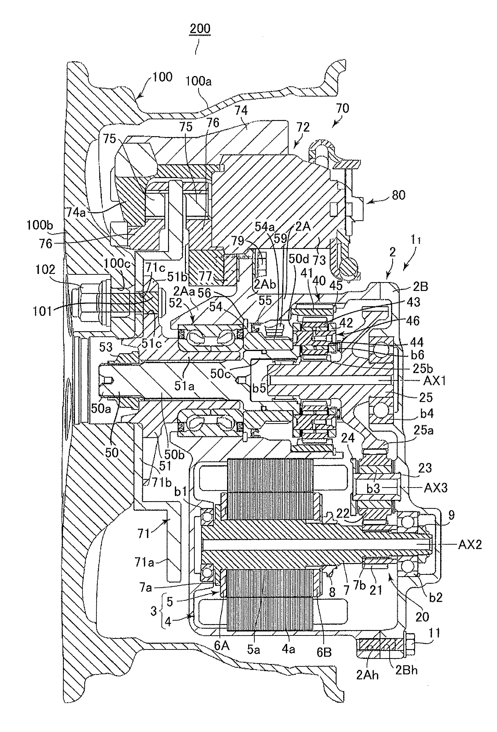
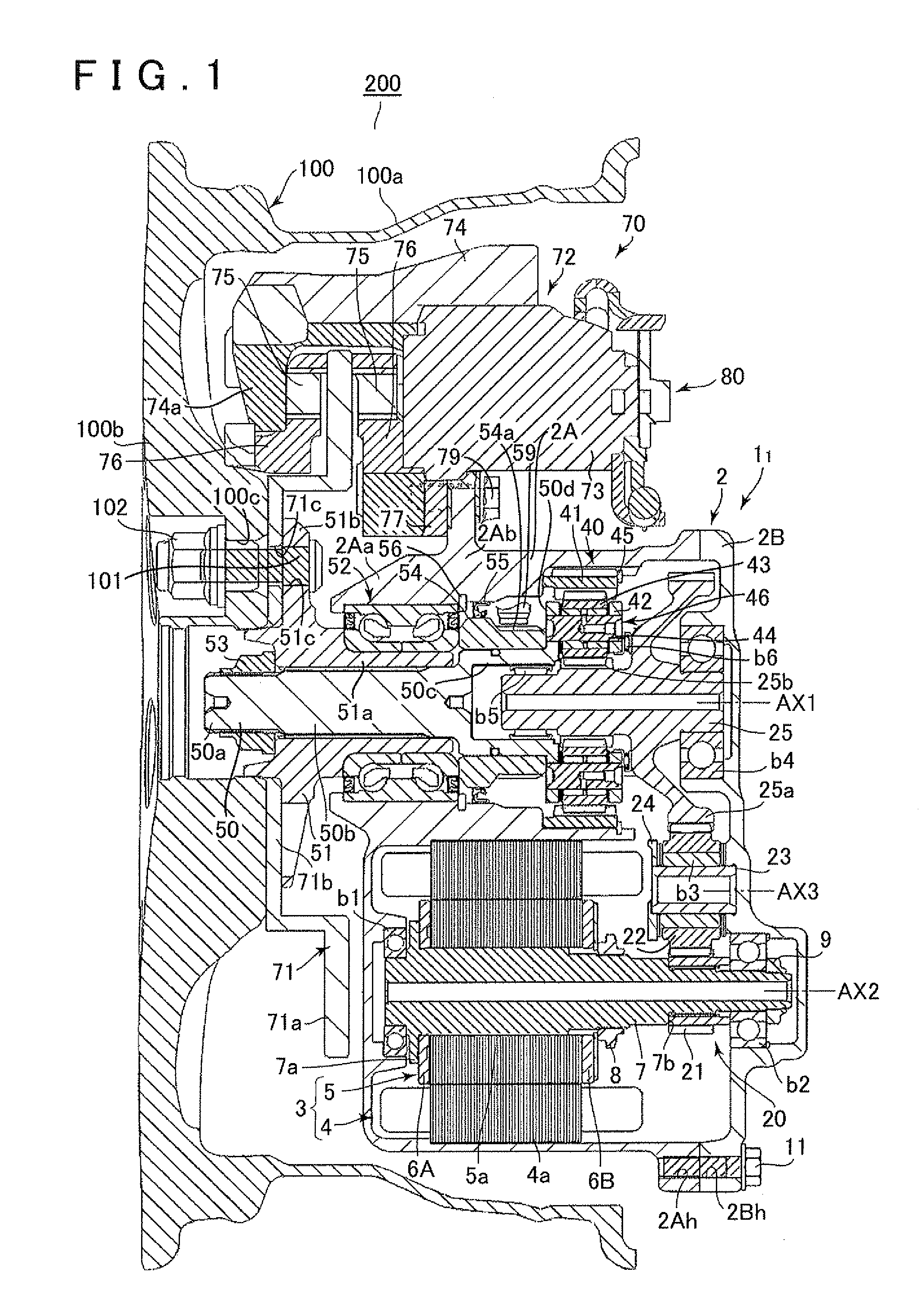
[0042]A first embodiment of the present invention will be described below with reference to FIGS. 1 to 5. First, an in-wheel motor drive device according to the present invention, and the structure of a vehicle wheel provided with the in-wheel motor drive device will be described with reference to FIGS. 1 and 2. Note that an in-wheel motor drive device 11 of the present embodiment is used as a drive device that is attached to inside a wheel of a rear vehicle wheel of a front-wheel-drive hybrid vehicle, and changes the vehicle to a four-wheel-drive mode. In addition to this, the in-wheel motor drive device 11 of the present embodiment may also be used, for example, as a drive device for an electric vehicle, a drive device for a series type of hybrid vehicle, or a drive device that is attached to inside a wheel of a front vehicle wheel of a rear-wheel-drive hybrid vehicle and changes the vehicle to a four-wheel-drive mode.

[0043]As shown in FIG. 1, the in-wheel motor drive device 11 is...

second embodiment

[0084]A second embodiment that partially modifies the first embodiment described above will be explained next with reference to FIGS. 6 to 9. Note that, in the description of the second embodiment, like reference symbols are used for parts identical to those of the first embodiment and such parts are not described further here.

[0085]The second embodiment has a configuration in which the attachment position of the suspension device 90 is modified compared to the first embodiment described above, and the output shaft 50 is directly supported by the suspension device 90 without the intervention of the case 2 of an in-wheel motor drive device 12. The joining portion 95 of the hub arm 92 of the suspension device 90 is interposed between the wheel hub 51 and the main case 2A, which shortens the main case 2A in the axial direction, and also shortens the motor 3 in the axial direction as a consequence. Thus, the motor 3 can be changed to a small induction motor with a small output.

[0086]Mor...

third embodiment

[0094]A third embodiment that partially modifies the first embodiment described above will be explained next with reference to FIG. 10. Note that, in the description of the third embodiment, like reference symbols are used for parts identical to those of the first embodiment and such parts are not described further here.

[0095]In the third embodiment, compared to the first embodiment described above, the motor 3 is changed from an induction motor to an IPM synchronous motor (permanent magnet embedded type motor). Accompanying the modification of the motor 3, in order to perform a control that detects the precise rotation position of the motor 3, a resolver device 30 is installed that detects the rotation position of the rotor shaft 7.

[0096]More specifically, the resolver device 30 of an in-wheel motor drive device 13 is configured to include a resolver rotor 32 that is fastened by a nut 33 that is more toward the proximal end portion of the rotor shaft 7 (the end portion on the right...


PUM


Abstract

An in-wheel motor drive device is attached to an inner side of a wheel of a vehicle wheel and drives the vehicle wheel. The in-wheel motor drive device includes a rotating electric machine; a transmission mechanism that transmits the rotation of the rotating electric machine; a speed reducing mechanism that reduces in speed the rotation transmitted by the transmission mechanism; and an output shaft that outputs the reduced-speed rotation of the speed reducing mechanism to the wheel. The speed reducing mechanism and the output shaft are disposed on a first axis coaxial with a center of the wheel. The rotating electric machine is disposed on a second axis parallel to the first axis, and the rotating electric machine and the speed reducing mechanism are positioned in a radial cross section perpendicular to the first axis and the second axis.

Description

INCORPORATION BY REFERENCE[0001]The disclosure of Japanese Patent Application Nos. 2011-069328 and 2011-165778 filed on Mar. 28, 2011 and Jul. 28, 2011, respectively, including the specifications, drawings and abstracts are incorporated herein by reference in their entirety.BACKGROUND OF THE INVENTION[0002]The present invention relates to an in-wheel motor drive device that is mounted in a hybrid vehicle, an electric vehicle, or the like. More specifically, the present invention relates to an in-wheel motor drive device that includes a rotating electric machine, and a speed reducing mechanism that reduces in speed the rotation of the rotating electric machine.DESCRIPTION OF THE RELATED ART [0003]Various vehicles mounted with a motor-generator (referred to simply as a. “motor” below) such as hybrid vehicles and electric vehicles have been proposed in recent years with the aim of realizing vehicles with better fuel economy and environmental performance. With respect to vehicles mounte...

Claims


Application Information

Patent Timeline
IPC IPC(8): B60K7/00
CPCB60K7/0007B60K17/046B60K2007/0038F16D65/12H02K7/116Y02T10/641B60K2007/0061B60L15/2045B60L2220/44Y02T10/64Y02T10/72
Inventor HIRANO, TAKAHISA
Owner AISIN AW CO LTD
Why Eureka
Try Eureka