Grating-enhanced optical imaging

a technology of enhanced optical imaging and grating, which is applied in the field of optical imaging, can solve the problem of not being able to provide information about the sample interior, and achieve the effect of improving resolution

Inactive Publication Date: 2012-10-04
THE BOARD OF TRUSTEES OF THE LELAND STANFORD JUNIOR UNIV
View PDF2 Cites 49 Cited by
  • Summary
  • Abstract
  • Description
  • Claims
  • Application Information

AI Technical Summary

Benefits of technology

[0012]In accordance with an example embodiment of the present disclosure, a coherent imaging technique is provided that utilizes a diffraction grating placed near the object to alias high spatial frequency information through the imaging system pupil. The resulting optical field in the image plane is detected by means of digital holography. Multiple measurements are taken with the grating shifted by a fraction of its period between exposures. Linear signal processing is then used to separate the aliased spectral components, and Fourier techniques are applied to reconstruct high-resolution images. Experimental results validate the approach, yielding an enhancement in resolution by a factor of 2.6 when using five diffracted beams (orders up to ±2).

Problems solved by technology

Additionally, the interior of the sample can be viewed and mapped in three dimensions using optical microscopy, whereas scanning electron microscopy and other scanned probe microscopies map only the surface of the is sample, and thus cannot provide information about the sample interior.

Method used


Image

  • Grating-enhanced optical imaging
  • Grating-enhanced optical imaging
  • Grating-enhanced optical imaging

Examples


Embodiment Construction

[0034]The present disclosure is believed to be applicable to a variety of different types of devices and processes, and the present disclosure has been found to be particularly suited for optical imaging applications. While the present disclosure is not necessarily limited to such applications, various aspects of the present disclosure may be appreciated through a discussion of various examples using this context.

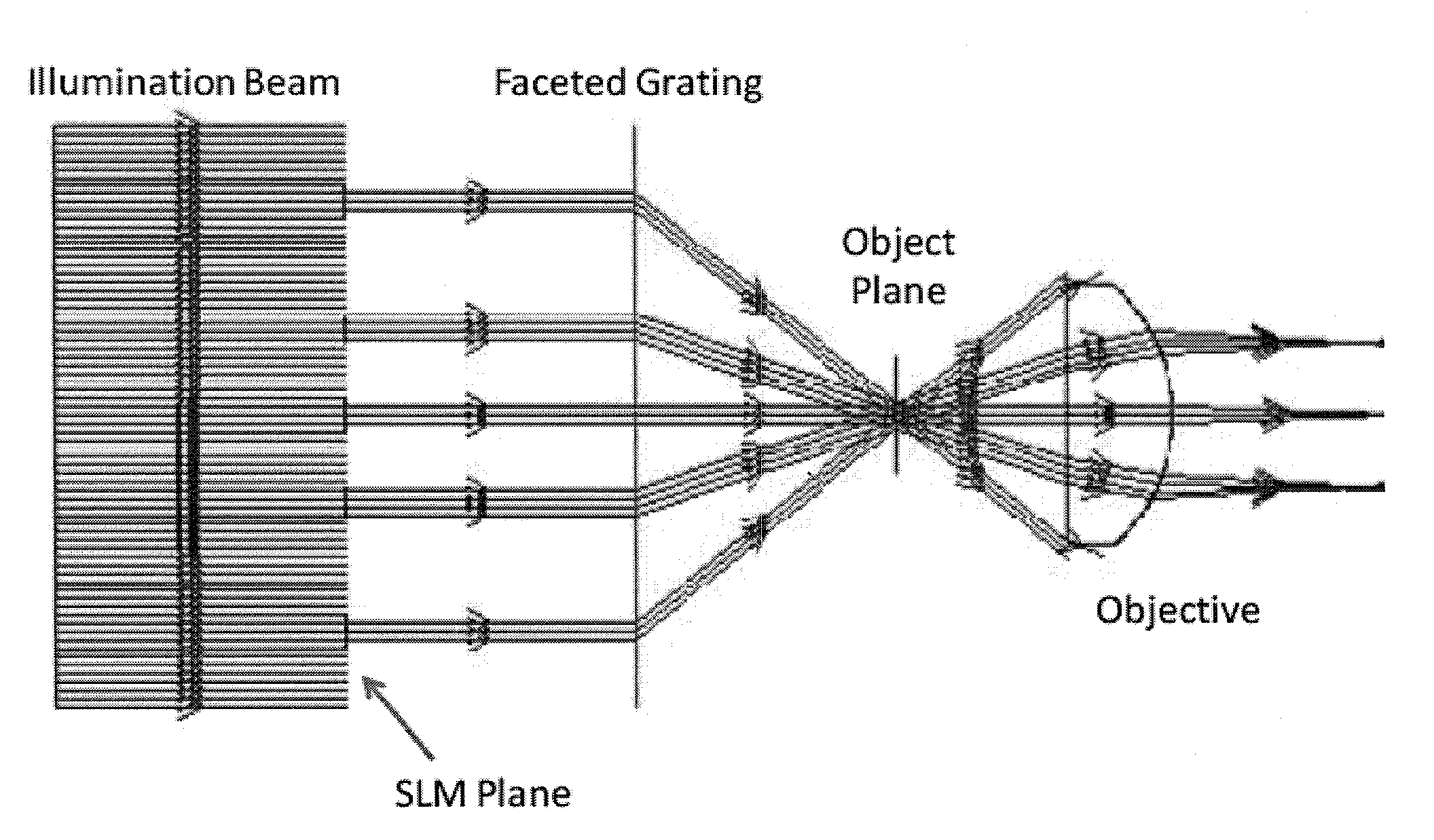
[0035]Consistent with certain example embodiments of the present invention, an optical imaging apparatus includes the following: a spatially coherent light source for illumination of an object; a grating component configured and arranged to generate N optical wavefronts containing the object's spatial amplitude variation; an imaging system having an object-space collection numerical aperture of NA0; and a light-responsive device configured and arranged to detect at least N complex-amplitude images of the composite wavefronts propagating from the object and received by the i...


PUM


Abstract

Systems, methods and devices are implemented for optical imaging. In one embodiment of the present disclosure, an optical imaging apparatus utilizes a laser-based coherent light source, and an optical device to pass grated light along an illumination direction from the laser-based coherent light source toward an object. Additionally, an illumination modulator is provided for changing angles at which the light, moving toward the object plane, reaches the object plane, and the light reaches the object plane at different angles. Further, the apparatus can include circuitry to process image-based data in response to and based on the light reaching the object plane at different angles for a user-viewable image of an object in proximity of the object plane.

Description

RELATED DOCUMENTS[0001]This patent document claims benefit under 35 U.S.C. §119 to U.S. Provisional Patent Application Ser. No. 61 / 471,205, entitled “Grating Enhanced Optical Imaging Systems” and filed on Apr. 4, 2011, and to U.S. Provisional Patent Application Ser. No. 61 / 619,193, entitled “Provisional Application Directed to Grating Enhanced Optical Imaging” and filed on Apr. 2, 2012; these patent documents and the Appendices filed in the underlying provisional applications are fully incorporated herein by reference.FIELD[0002]Aspects of the present disclosure relate generally to optical imaging such as exemplified by methods and systems benefiting from grating-enhanced imaging.BACKGROUND[0003]Aspects of the present disclosure relate generally to optical imaging such as exemplified by methods and systems benefiting from grating-enhanced imaging.[0004]Optical microscopy has experienced a significant growth in the medical and biological sciences during the last decade. The increased...

Claims


Application Information

Patent Timeline
Patent Type & Authority Applications(United States)
IPC IPC(8): G01B9/02
CPCG01B2210/56G01N21/956G01N2021/95676G01B9/02047G02B21/06G02B27/58G02B21/002
Inventor WILDE, JEFFREY P.ELDAR, YONINA C.GOODMAN, JOSEPH W.
Owner THE BOARD OF TRUSTEES OF THE LELAND STANFORD JUNIOR UNIV
Why Eureka
Try Eureka