
Wide-angle lens and system enclosing wide-angle lens

a wide-angle lens and system-enclosed technology, applied in the field of wide-angle lenses, can solve the problems of difficult to reduce the effective aperture of the first lens, insufficient correction of chromatic aberration for both the first and the second lenses, and insufficient compactness of the wide-angle lenses, etc., to achieve high performance and high performance.

Inactive Publication Date: 2012-10-04
SATOSHI DO
View PDF3 Cites 13 Cited by
  • Summary
  • Abstract
  • Description
  • Claims
  • Application Information

AI Technical Summary

Benefits of technology

The invention is a wide-angle lens system that has a short optical length, a long back focus, and ideal image quality. The lens system includes a first lens, a second lens, a third lens, an aperture stop, and a fourth lens arranged in this order from the object to the image. The first lens has negative refractive power, the second lens has positive refractive power, the third lens has positive refractive power, and the fourth lens has positive refractive power. The lens system can be used in a compact and high-performance camera system.

Problems solved by technology

Therefore correction of chromatic aberration is insufficient for both the first and second wide-angle lenses.
This makes it difficult to decrease the effective aperture of the first lens disposed in the first place from the object.
Since it cannot be avoided making the effective aperture of the first lens large, the third to sixth wide-angle lenses cannot be sufficiently compact.
In the case of the seventh wide-angle lens, a lens having negative refractive power is used for the second lens disposed in the second place from the object, among the four single lenses, which makes it difficult to decrease the effective aperture of the first lens disposed in the first place from the object.
Therefore just like the case of the third to sixth wide-angle lenses, it is difficult to make the seventh wide-angle lens sufficiently compact.

Method used


Image

  • Wide-angle lens and system enclosing wide-angle lens
  • Wide-angle lens and system enclosing wide-angle lens
  • Wide-angle lens and system enclosing wide-angle lens

Examples


first embodiment

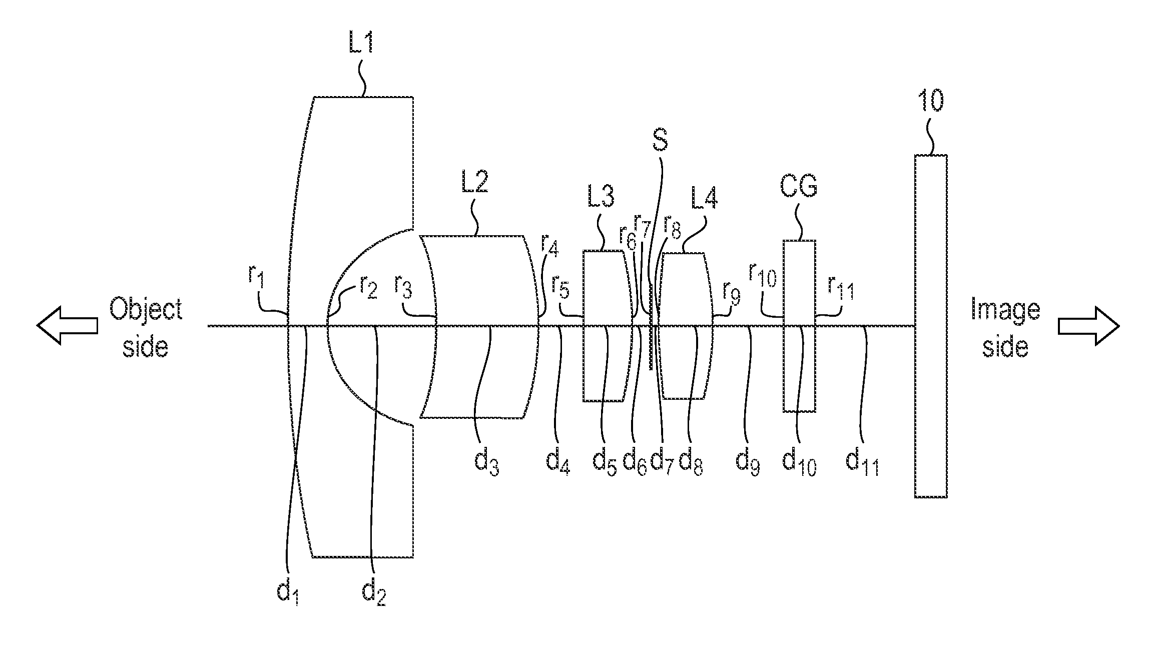
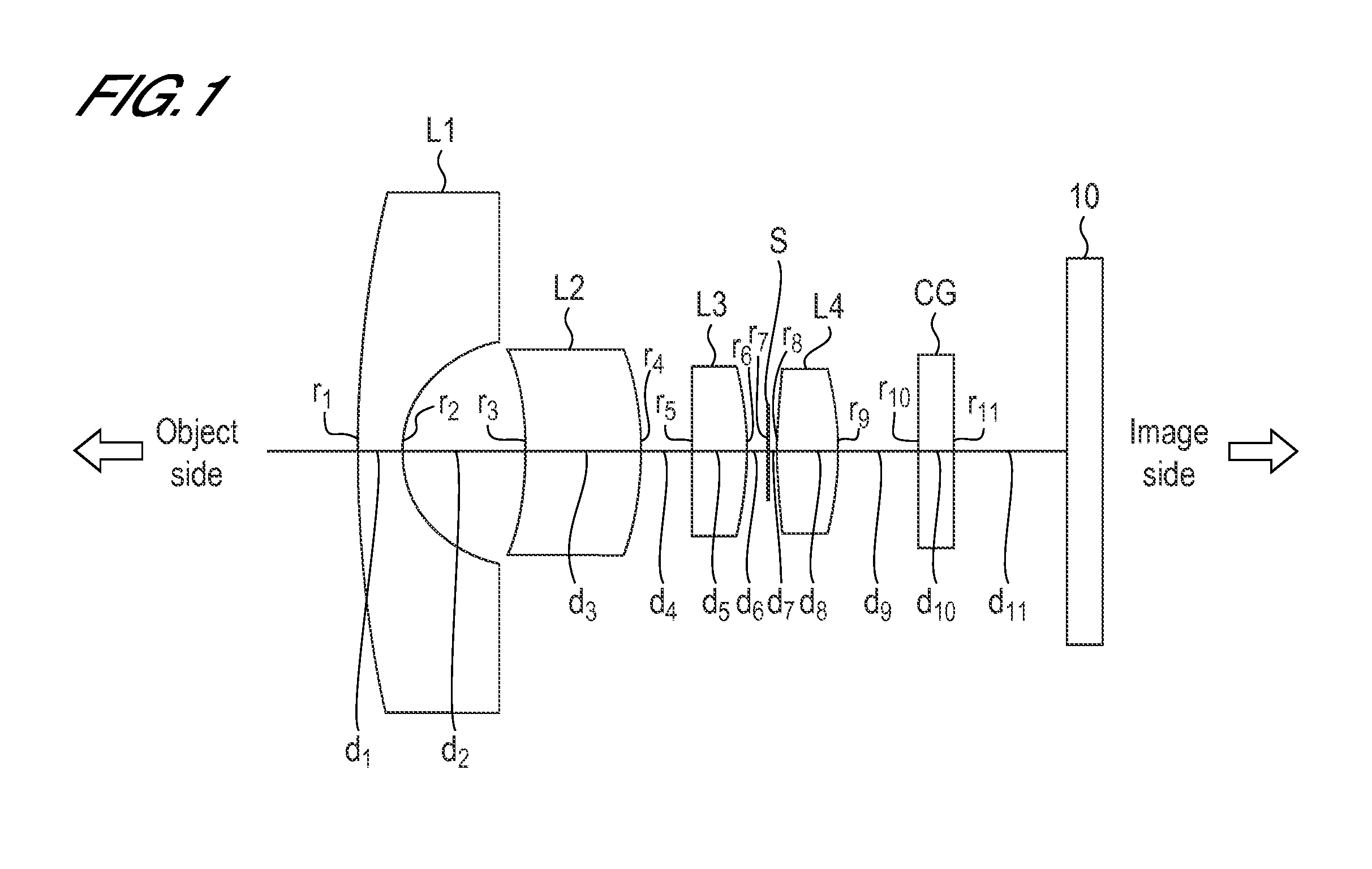
[0074]FIG. 1 is a diagram depicting a configuration of a wide-angle lens according to an embodiment of this invention. The symbols of the surface number, surface distance or the like defined in FIG. 1 are commonly used for FIG. 2, FIG. 6, FIG. 10 and FIG. 14. In FIG. 1, the aperture portion of the aperture stop is indicated as a segment. This is because in order to define the distance from the lens surface to the aperture stop surface, the intersection of the aperture stop surface and the optical axis must be clearly indicated. In FIG. 2, FIG. 6, FIG. 10 and FIG. 14, which are optical path diagrams of the imaging lenses of Example 1-1 to Example 1-4 respectively, the aperture portion of the aperture stop is opened, and the main body of the aperture stop, for blocking light, is illustrated using a half line starting at the edge of the aperture portion, unlike FIG. 1. This is because the aperture portion of the aperture stop must be shown in an opened state, in order to draw such rays...

example 1-1

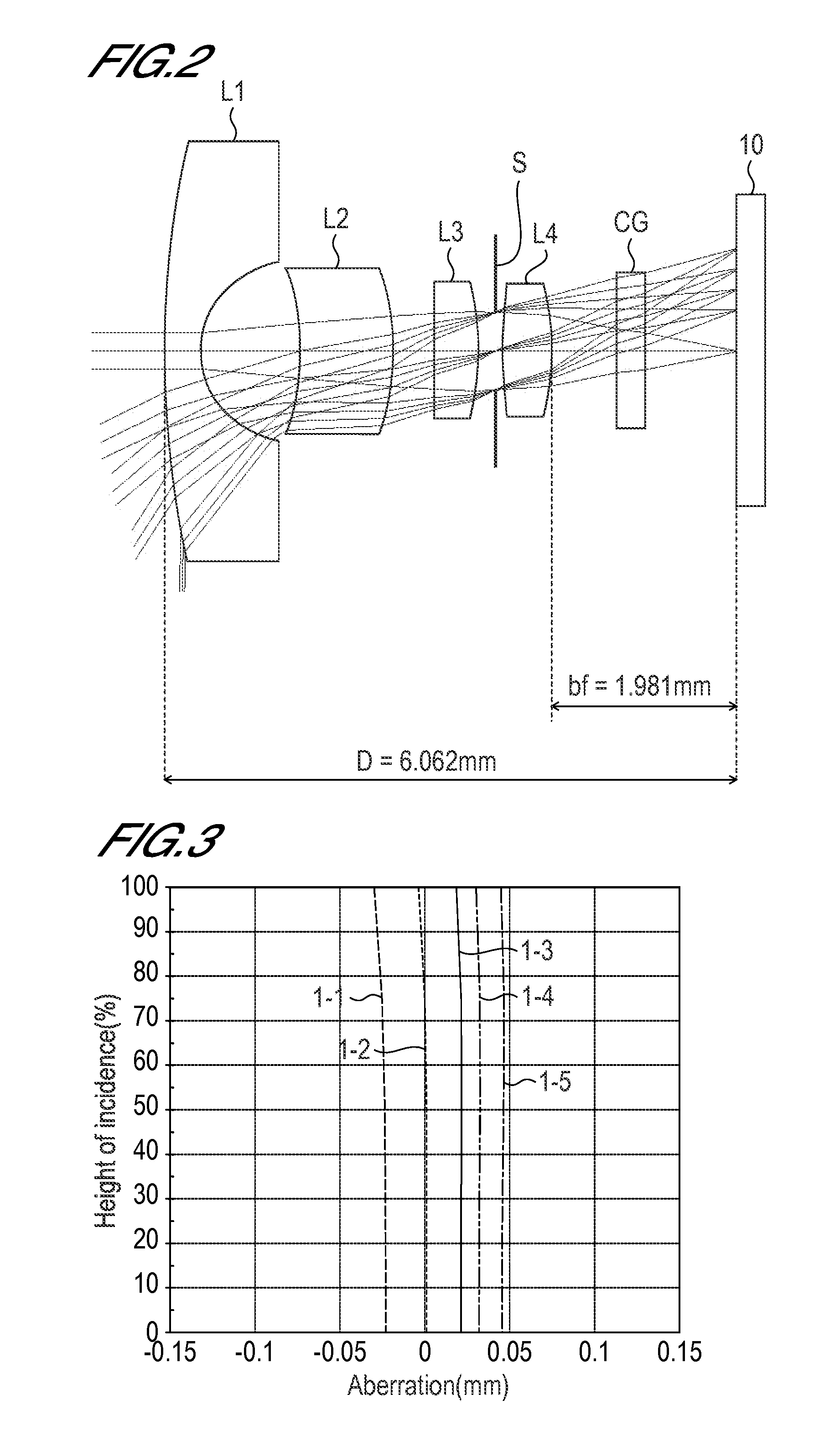
[0094]FIG. 2 is a cross-sectional view depicting a wide-angle lens according to Example 1-1. As FIG. 2 illustrates, the wide-angle lens of Example 1-1 comprises, in order from the object to the image, a first lens L1, a second lens L2, a third lens L3, an aperture stop S and a fourth lens L4.

[0095]The first lens L1 is meniscus lens having negative refractive power, of which convex surface faces the object. The second lens L2 is a meniscus lens having positive refractive power, of which convex surface faces the image. The third lens L3 and the fourth lens L4 are lenses having positive refractive power. Both surfaces of the second lens L2 and both surfaces of the third lens L3 are aspherical. As FIG. 2 illustrates, in the wide-angle lens of Example 1-1, the back focus bf with respect to the focal length 1.00 mm is 1.981 mm in a state where the cover glass CG is inserted. In other words, a sufficient length of back focus is secured.

[0096]The full aperture F number is 2.60, that is, the...

example 1-2

[0104]FIG. 6 is a cross-sectional view depicting a wide-angle lens according to Example 1-2. As FIG. 6 illustrates, the wide-angle lens of Example 1-2 comprises, in order from the object to the image, a first lens L1, a second lens L2, a third lens L3, an aperture stop S and a fourth lens L4.

[0105]The first lens L1 is a meniscus lens having negative refractive power, of which convex surface faces the object. The second lens L2 is a meniscus lens having positive refractive power, of which convex surface faces the image. The third lens L3 and the fourth lens L4 are lenses having positive refractive power. The object side surface of the first lens L1, both surfaces of the second lens L2, and both surfaces of the third lens L3, are aspherical. As FIG. 6 illustrates, in the wide-angle lens of Example 1-2, the back focus bf with respect to the focal length 1.00 mm is 1.978 mm in a state where the cover glass CG is inserted, in other words, sufficient length of back focus is secured.

[0106]...


PUM


Abstract

Conventional wide angle lenses each do not have such features that an optical length is short, a back focus is long to the extent possible, a good image is obtained, and sufficient brightness is provided. In other words, it is difficult to perform sufficient correction of chromatic aberration and achieve sufficient downsizing. Provided is a wide angle lens provided with a first lens L1, a second lens L2, a third lens L3, an aperture stop S, and a fourth lens L4. The wide angle lens is configured by arranging the first lens L1, the second lens L2, the third lens L3, the aperture stop S, and the fourth lens L4 in this order from the side of an object toward the side of an image. The first lens L1 is a meniscus lens having a negative refractive power, the convex surface of which faces the side of the object. The second lens L2 is a meniscus lens having a positive refractive power, the convex surface of which faces the side of the image. The third lens L3 and the fourth lens L4 are lenses having the positive refractive power.

Description

TECHNICAL FIELD[0001]The present invention relates to an imaging lens, and more particularly to a wide-angle lens which is suitable for an imaging device using such a solid-state image sensor as an on-vehicle camera (e.g. camera for rear monitoring, camera for driving recorder), monitoring camera, intercom camera, crime prevention camera, camera embedded in portable equipment, conference camera, TV camera, endoscope and miniature medical capsule. The present invention also relates to a semiconductor device enclosing a solid-state image sensor which is a semiconductor, and devices and systems related to this semiconductor device.BACKGROUND ART[0002]Many wide-angle lenses suitable for the above mentioned applications have been proposed, and a wide-angle lens configured as a lens system in which a plurality of single lenses are combined has been disclosed in documents. In order to create a compact imaging device, a wide-angle lens to be installed is also demanded to be compact, hence l...

Claims


Application Information

Patent Timeline
Patent Type & Authority Applications(United States)
IPC IPC(8): G02B13/18
CPCG02B13/005G02B13/18G02B13/06
Inventor DO
Owner SATOSHI DO
Learn More