Self-contained emergency spent nuclear fuel pool cooling system

a nuclear fuel pool and self-contained technology, applied in nuclear engineering, nuclear elements, greenhouse gas reduction, etc., can solve the problems of increasing the cost of a shutdown operation, not having sufficient cooling capacity to remove the high level of residual heat generated, and affecting the efficiency of the shutdown operation

Active Publication Date: 2012-10-04
WESTINGHOUSE ELECTRIC CORP
View PDF30 Cites 35 Cited by
  • Summary
  • Abstract
  • Description
  • Claims
  • Application Information

AI Technical Summary

Benefits of technology

[0010]These and other objects are achieved by the embodiments described herein which provide a self-powered residual heat removal system that can be transported to and rapidly connected to a spent nuclear fuel pool at least partially filled with a liquid, such as water or borated water. The residual heat removal system includes a cooling conduit disposed within the spent fuel pool within the liquid in which the spent fuel is submerged, having an interior of the cooling conduit isolated from the liquid within the spent nuclear fuel pool. A coolant fluid reservoir, remote from the spent fuel pool, is connected to the cooling conduit by a coupling line through which a coolant can be circulated from the coolant fluid r

Problems solved by technology

The heat removal capacity of this system is necessarily large.
This is due to the fact that the spent fuel pool, the eventual storage place for the fuel, has a permanently installed cooling system, which does not have sufficient cooling capacity to remove the high level of residual heat generated by the fuel immediately following plant shutdown.
This cool down time increases the facility's overall shutdown period, thus, increasing the cost of a shutdown operation, resulting in lost revenues, as well as the cost of replacement power purchased during the shutdown.
On the other hand, the cost of such an auxiliary

Method used


Image

  • Self-contained emergency spent nuclear fuel pool cooling system
  • Self-contained emergency spent nuclear fuel pool cooling system
  • Self-contained emergency spent nuclear fuel pool cooling system

Examples


Embodiment Construction

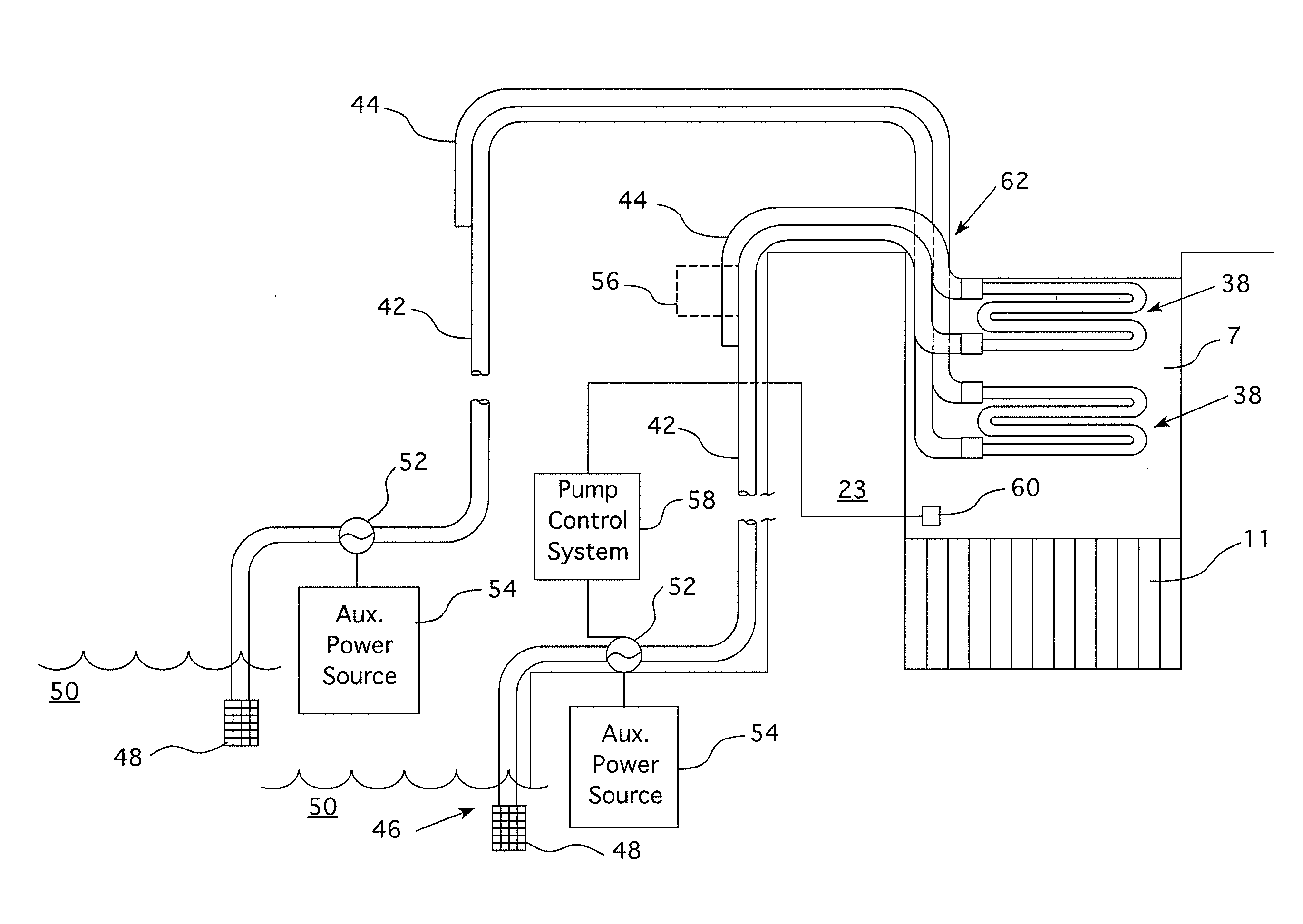
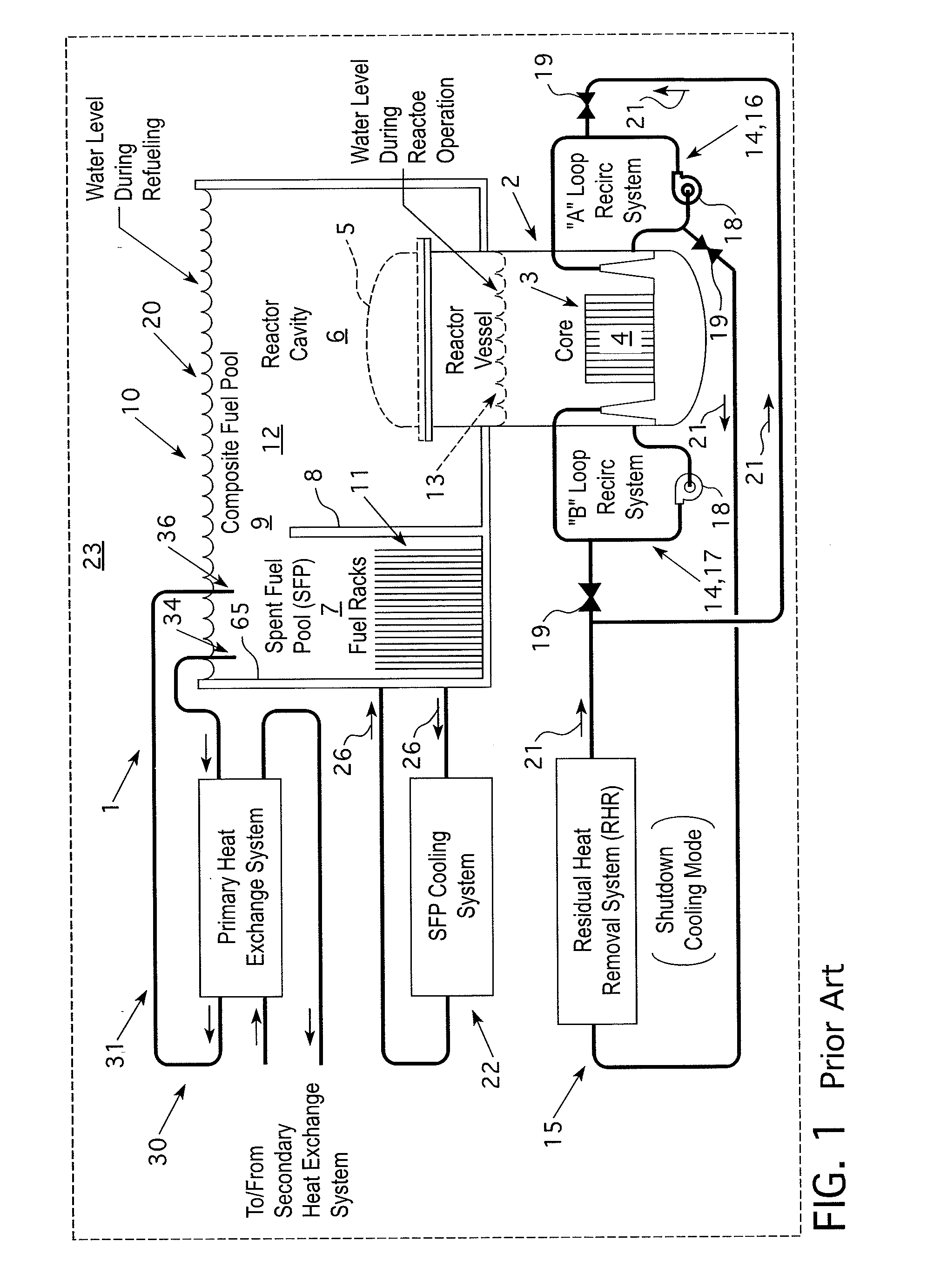
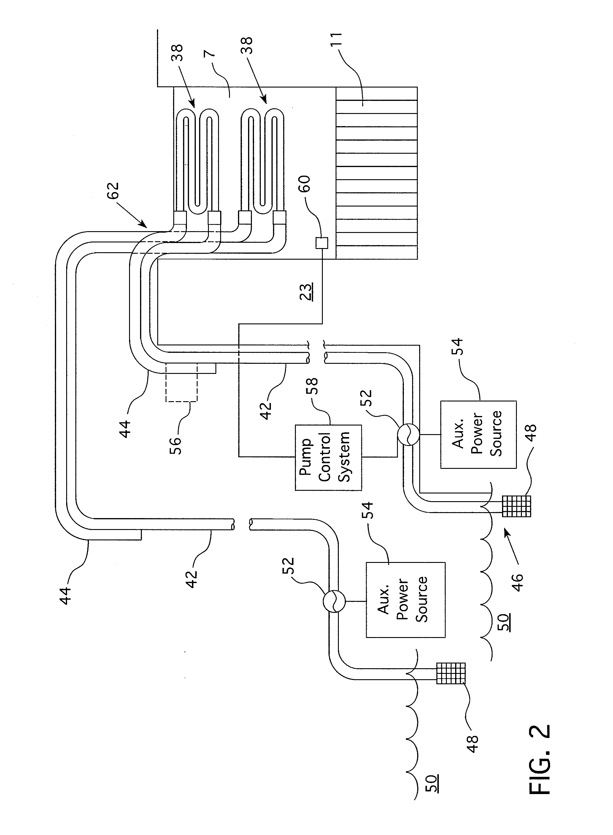
[0016]As shown in FIG. 1, in a typical light water reactor nuclear power generating facility, only the pertinent parts of which are shown, a reactor building 23 contains a reactor vessel 2 which contains a core 3, which comprises numerous elements of nuclear fuel 4, usually in the form of fuel bundles, commonly referred to as fuel assemblies. During power generating operations, reactor vessel 2 is closed by the top or head 5. Reactor vessel 2 is positioned within a reactor cavity 6, which in some designs is fluidly connected to a spent fuel pool 7 during outages. However, even in designs where the reactor cavity is connected to the spent fuel pool during outages, containment isolation during operation requires that the spent fuel pool water be separate from the water in the refueling cavity and reactor cavity. In the facility embodiment shown in FIG. 1, the spent fuel pool 7 is separated from the reactor cavity by a wall 8 having a closable opening 9, closable by a gate (not shown) ...


PUM


Abstract

An auxiliary system for cooling a spent nuclear fuel pool through a submersible heat exchanger to be located within the pool. In each train or installation, a single loop or series of loops of cooling fluid (e.g., sea water or service water) is circulated. The system is modular, readily and easily installed during an emergency and can be self operating with its own power source. Multiple trains may be used in parallel in order to accomplish the required degree of spent fuel pool cooling required.

Description

CROSS REFERENCE TO RELATED APPLICATION[0001]This application claims priority to Provisional Application Ser. No. 61 / 469,184, filed Mar. 30, 2011, entitled SELF-OPERATING EMERGENCY SPENT FUEL POOL COOLING SYSTEM.BACKGROUND[0002]1. Field[0003]This invention relates generally to cooling systems used to cool water in a nuclear reactor power generating facility and, more particularly, to a temporary cooling system designed to supplement existing cooling systems for the Spent Fuel Pool and accommodate emergency conditions experienced in such a facility.[0004]2. Related Art[0005]In nuclear power generating facilities, a reactor vessel housing nuclear fuel and water is positioned in what is commonly referred to as a refueling cavity or a reactor cavity. During power generation, a primary fluid coolant, normally water, is heated by the nuclear fuel, and the heat is used to generate steam for electric power generation. During shutdowns for refueling and other periods when the reactor is not o...

Claims


Application Information

Patent Timeline
IPC IPC(8): G21C9/00
CPCG21C19/07Y02E30/40G21D1/04G21C19/08G21D1/02G21C15/182Y02E30/30Y02E30/00G21F5/10
Inventor LLOYD, TIMOTHY M.RASMUSSEN, DAVIDKULESZA, JOEL
Owner WESTINGHOUSE ELECTRIC CORP
Why Eureka
Try Eureka