Turbine housing made of sheet metal

a technology of turbine housing and sheet metal, which is applied in the direction of machines/engines, stators, liquid fuel engines, etc., can solve the problems of cracks and the like cracks and the like may be easily caused, and the strength decreases, so as to avoid the risk of cracks and the like due to thermal stress and thermal fatigue in the neighborhood of the tongue part, and reduce the strength. , the effect of avoiding cracks and the lik

Active Publication Date: 2012-10-04
MITSUBISHI HEAVY IND LTD
View PDF2 Cites 11 Cited by
  • Summary
  • Abstract
  • Description
  • Claims
  • Application Information

AI Technical Summary

Benefits of technology

[0039]According to the first disclosure of the present invention, when the double-wall structure is applied to an area in the neighborhood of the tongue part, the functions against pressures as well as against thermal load can be separated in the neighborhood of the tongue part. The risk of the crack occurrence and the like due to thermal stresses and thermal fatigue in the neighborhood of the tongue part can be avoided.
[0040]Further, according to the second disclosure of the present invention, the welding-joint line is shifted apart from a location where the tongue part is formed in the turbine rotation axis direction

Problems solved by technology

Thus, since the rapid heating and cooling of the tongue part as a winding end part of the scroll part 02 are repeated, the cracks of the tongue part may be easily caused, the cracks being attributable to not only the strength decrease due to the welding of the butt-joined sheet metal members but also the thermal stresses.
Further, also in the scroll structure disclosed by Patent Reference 2, the sheet metal members are butt-joined so as to form the scroll part; as explained in the case of Patent

Method used


Image

  • Turbine housing made of sheet metal
  • Turbine housing made of sheet metal
  • Turbine housing made of sheet metal

Examples


Embodiment Construction

[0050]Hereafter, the present invention will be described in detail with reference to the modes or embodiments shown in the figures. However, the dimensions, materials, shape, the relative placement and so on of a component described in these modes or embodiments shall not be construed as limiting the scope of the invention thereto, unless especially specific mention is made.

(First Mode)

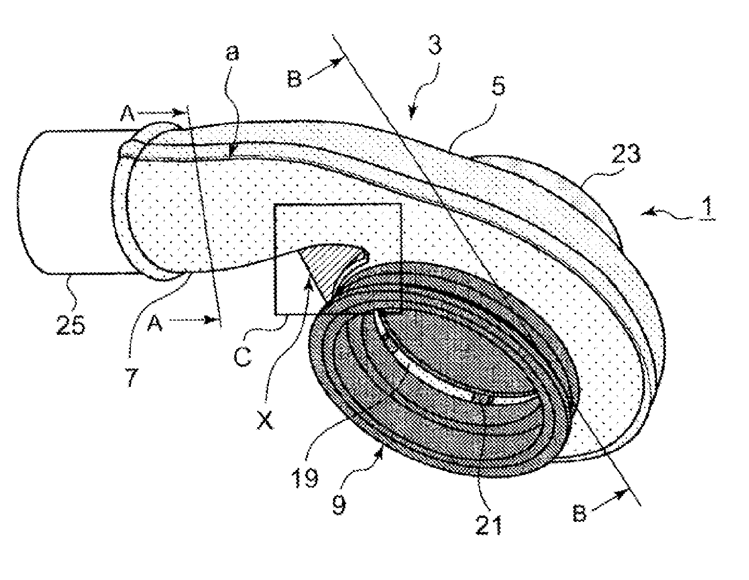
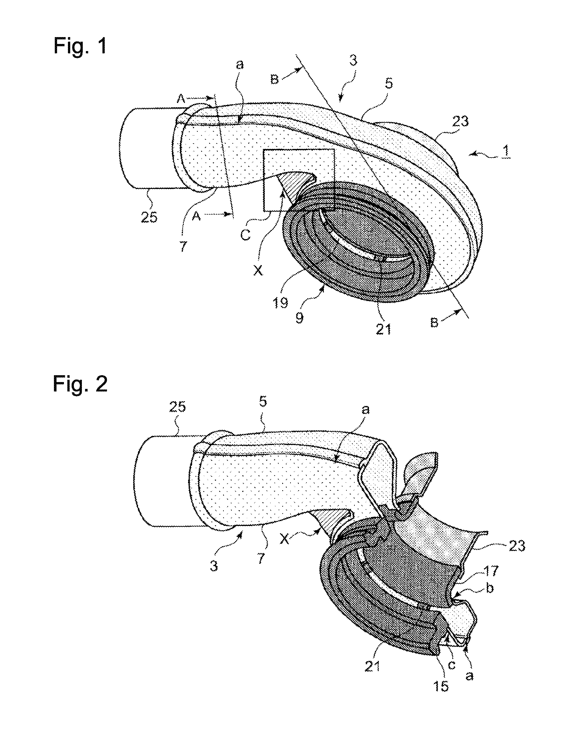
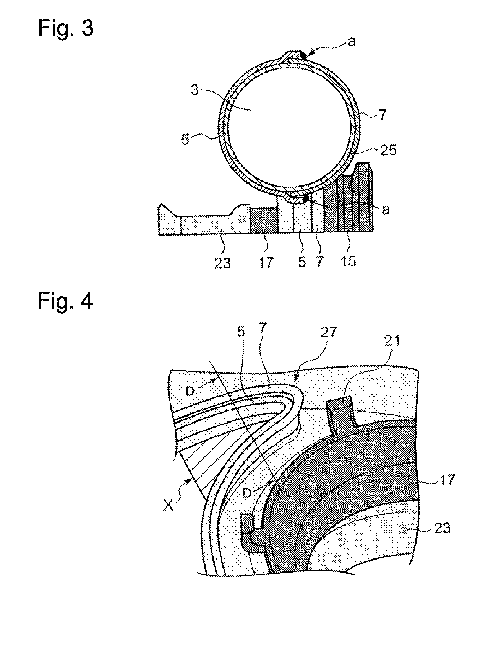
[0051]Based on FIGS. 1 to 5, a turbine housing made of sheet material according to a first mode of the present invention is now explained.

[0052]As shown in FIGS. 1 and 2, the turbine housing 1 made of sheet material mainly includes, but not limited to, a scroll part 3, a center core part 9 and the outlet pipe part 23. Further, the scroll part 3 includes, but not limited to, a first scroll part 5 and a second scroll part 7, the scroll parts 5 and 7 facing each other. Weld-bonding the four members forms the turbine casing 1.

[0053]The scroll part 3 forming a spiral gas passage is configured by butt-joini...


PUM


Abstract

In the neighborhood area X of the tongue part 27 forming the winding end part of the scroll part 3, the wall part members 31 are provided on both the sides of the welding part (the facing part) ‘a’ of the first scroll part 5 and the second scroll part 7, wherein: the wall part members 31 encloses the welding part (the facing part) ‘a’ and forms the gas-tight space 33; and, the outer circumference wall which enclose the facing part and forms a gas-tight space configure a double-wall structure.

Description

BACKGROUND OF THE INVENTION[0001]1. Field of the Invention[0002]The present invention relates to a turbine housing structure of a sheet metal structure, the turbine housing being used for a turbocharger which produces a turbocharged pressure for an engine by use of exhaust gas energy of the engine. The present invention especially relates to the turbine housing structure in which cracks and the like due to thermal stresses are prevented from occurring in a tongue part at a scroll winding end part.[0003]2. Background of the Invention[0004]Conventionally, turbochargers which enhance power output of an engine by supplying a pressurized air into the intake manifold of the engine by use of the exhaust gas energy discharged from the engine are known. When the turbocharger is mounted as a vehicle use, it is required to reduce the weight of the turbocharger especially in view of the tendency regarding fuel consumption improvement in recent years; thus, instead of the conventional turbine ho...

Claims


Application Information

Patent Timeline
IPC IPC(8): F04D29/44
CPCF01D9/026F05D2220/40F01D25/145F05D2230/232F05D2230/54F02B39/00F01D25/26
Inventor WATANABE, DAIGOEBISU, MOTOKI
Owner MITSUBISHI HEAVY IND LTD
Why Eureka
Try Eureka