
System and Method for Creating a Graphical Control Programming Environment

a programming environment and programming system technology, applied in the direction of program control, electric controllers, instruments, etc., can solve the problems of high cost, large resource consumption, and change in control process, and achieve the effect of operation, and reducing the cost of control system maintenan

Active Publication Date: 2012-10-04
RADL BRAD
View PDF83 Cites 18 Cited by
  • Summary
  • Abstract
  • Description
  • Claims
  • Application Information

AI Technical Summary

Benefits of technology

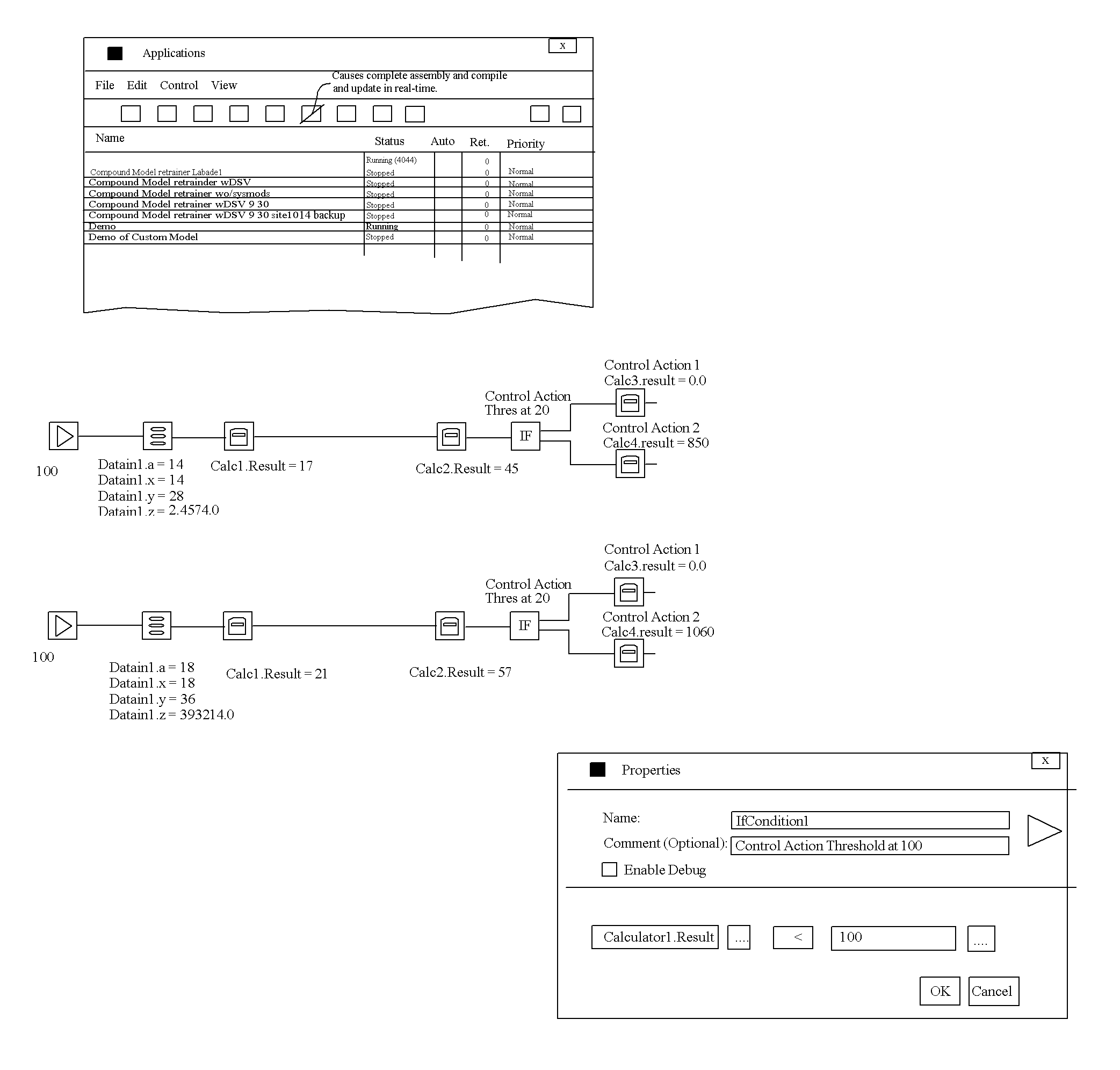
[0012]The present invention relates a system and method for generating modeling software for processing control, such as power plant control or other industrial control, using models such as expert systems, fuzzy logic, genetic optimization algorithms, and neural networks to convert sensor data into actionable data, information and / or diagnostics. The present invention includes a graphical programming environment, graphical programming tools, graphical user interface (GUI), visual feedback, real-time refresh, run-time object swap, logic standby (safety recovery), modeling and optimization to allows a user to create a control system for an industrial process, and that allows the user to change the process without any manual compile, assemble or load steps other than a save and refresh pushbutton.
[0014]The present invention eliminates the need for a programmer, and allows a user, maybe an expert, to directly implement logic, models, optimizations, and the like into a program readily modified, tested, changeable and adopted for use. The final control programs and tools so developed can be implemented in real-time actionable data solutions (such as direct control) and for off-line data analysis, what-if scenarios, optimization scenarios and other common tasks of interrogating data.

Problems solved by technology

Modeling and optimization tend to be resource intensive, and the more advanced the programmer, generally the more efficient the operation of the code.
One of the challenges is that often the control process is changing, or evolving, being modified or is otherwise dynamic.
It would be advantageous to encode or program this knowledge into automation systems, but this tends to be expensive, involving layers of people to get the knowledge from the ‘knower's head’ to a program such as an expert system, where it can be tested.

Method used


Image

  • System and Method for Creating a Graphical Control Programming Environment
  • System and Method for Creating a Graphical Control Programming Environment
  • System and Method for Creating a Graphical Control Programming Environment

Examples


Embodiment Construction

[0030]The present invention relates to graphical-based programming that permits creation of control models, optimizers, logic, expert logic, fuzzy logic, processing logic, data manipulation, data handling, data processing, toolbars, customized user interfaces, distributed processing of applications and routines as well as cloud enabled applications and routines. The present invention enables users to change logic and evaluate the impact on the next scheduled (time or trigger based) execution of that change in logic. The system accommodates the use of external code of any type with incorporation of this code into a system utilizing objects in a system designed for object serialization and reflection.

[0031]Prior art systems have numerous limitations known in the art, and because of these limitations, various graphical programming environments now exist which allow a user to construct a graphical program or graphical diagram. Often these are termed as block diagrams. Graphical programm...


PUM


Abstract

A system and method for generating modeling software for processing control, such as power plant control, cement plant or other industrial control application, using models such as expert systems, fuzzy logic, genetic optimization algorithms, and neural networks to convert sensor data into actionable data, information and / or diagnostics. The present invention includes a graphical programming environment, graphical programming tools, graphical user interface (GUI), visual feedback, real-time refresh, run-time object swap, logic standby (safety recovery), modeling and optimization to allows a user to create a control system for an industrial process, and that allows the user to change the process without any manual compile, assemble or load steps other than a save and refresh pushbutton.

Description

BACKGROUND[0001]1. Field of the Invention[0002]The present invention relates generally to a system and method for building advanced and supervisory control systems using a graphical programming environment, and in particular a system for processing information and using models, expert type logic, genetic algorithms and optimization algorithms to convert sensor data into actionable data, information, and / or diagnostics.[0003]2. Description of the Prior Art[0004]Computing technology is continuing to advance at a rapid pace, permitting more powerful algorithms and complex strategies to be implemented to efficiently run a control process or businesses. Increasingly, the shift of automation is from mundane repetitive tasks to those of high order complexity that are simplified by human operators to achieve rapid response. The increasingly complex tasks can be automated to assist, complement or take direct control over industrial processes and business operation which before could only be ...

Claims


Application Information

Patent Timeline
Patent Type & Authority Applications(United States)
IPC IPC(8): G05B19/05
CPCG05B19/042G05B2219/23258G06F8/34
Inventor RADL, BRAD
Owner RADL BRAD
Learn More