Method and program for calculating correction value for machine tool

a technology of correction value and machine tool, applied in the field of method and program for calculating correction value of machine tool, can solve the problems of large load on the rotational axis, trouble with the machine tool, and inability to adjust the positional error of the tool center point, so as to prevent excessive load on the rotational axes, less calculation, and the effect of reducing the load

Active Publication Date: 2012-10-04
OKUMA CORP
View PDF5 Cites 14 Cited by
  • Summary
  • Abstract
  • Description
  • Claims
  • Application Information

AI Technical Summary

Benefits of technology

[0024]In accordance with the present invention, the correction value for the rotational axis that does not depend on the rotational axis command values can be calculated out by use of a simple computing method with less calculation. This allows correction of the positional error of the tool center point of a machine tool such as a five-axis machine due to the geometric errors and also allows correction of the orientation error of the tool due to the geometric errors.
[0025]Furthermore, in accordance with the present invention, the correction value for the rotational axis is retained without update in a state where the rotational axis has been clamped, thereby enabling correction of the positional error of the tool center point while preventing excessive loads on the rotational axes.

Problems solved by technology

This results in a large load on the rotational axis due to twisting or the like, and further results in a rotational error due to deformation of a member, thus impairing accuracy.
Furthermore, a motor that drives the rotational axis may overheat and thus may result in trouble with the machine tool.

Method used


Image

  • Method and program for calculating correction value for machine tool
  • Method and program for calculating correction value for machine tool
  • Method and program for calculating correction value for machine tool

Examples


first embodiment

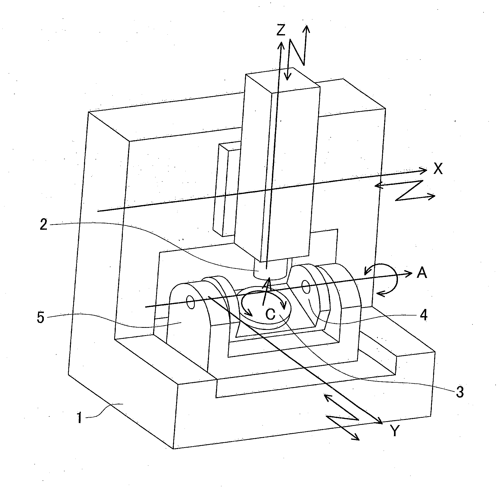
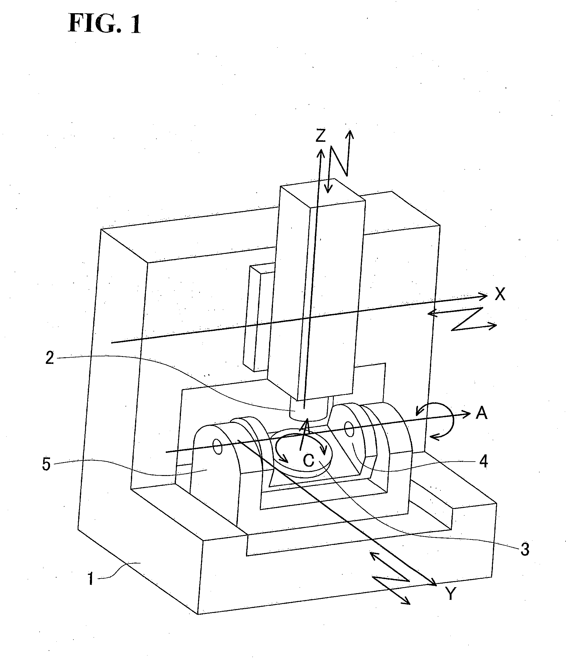
[0033]FIG. 3 illustrates an example of a numerical control system 10 for performing a method of controlling in accordance with the first embodiment of the present invention. A command value generating device 11 generates command values for driving axes when a machining program G is input. A correction value computing device 12 computes correction values for axes on the basis of the command values generated by the command value generating device 11. A servo command value converting device 13 receives the sum of the respective command values and correction values, then computes servo command values of the respective axes, and sends the servo command values to servo amplifiers 14a to 14e of the respective axes. The servo amplifiers 14a to 14e of the respective axes drive servo motors 15a to 15e, thereby controlling the relative position and orientation of the spindle head 2 with respect to the table 3.

[0034]Next, geometric errors will be described. The geometric errors are defined as r...

second embodiment

[0063]A second embodiment of the present invention will be next described. Like elements to the first embodiment will be denoted by like numerals and symbols, and descriptions of those will be appropriately omitted. Like elements to the first embodiment include the numerical control system 10 (FIG. 3) and the (final) geometric errors.

[0064]On the other hand, clamp mechanisms which are not shown are provided to both the A and C axes in a five-axis machine of the second embodiment. The clamp mechanism clamps the rotational axis during, before, or after machining to secure rigidity in machining. The clamp mechanism is controlled by a computer to clamp or unclamp the rotational axis. Either the A axis or the C axis may not include the clamp mechanism. Furthermore, machine tools with different numbers of rotational axes may have clamped axes for all the rotational axes or may have the clamp mechanisms for some of the rotational axes.

[0065]Next, a method of computing a correction value fo...


PUM

PropertyMeasurementUnit
degrees of freedomaaaaaaaaaa
rigidityaaaaaaaaaa

Abstract

The present invention provides a method of computing a correction value for the machine tool having two or more translational axes and one or more rotational axes for correcting error in a position and an orientation of the tool with respect to a workpiece due to the geometric error. The method includes a rotational axis correction value computing step (S3) for computing a correction value for the rotational axis by use of a geometric parameter representing the geometric error, and a translational axis correction value computing step (S4) for computing a correction value for the translational axis by use of a command value for each of the rotational axes, a command value for each of the translational axes, and the geometric parameter.

Description

BACKGROUND OF THE INVENTION[0001]This application claims the benefit of Japanese Patent Application Numbers 2011-083078 and 2011-083079 filed on April 4, the entirety of which is incorporated by reference.TECHNICAL FIELD[0002]The present invention relates to a method of computing a correction value for correcting a geometric error of a machine tool having translational axes and rotational axes and a program thereof.BACKGROUND ART[0003]FIG. 1 is a schematic diagram of an example of a machine tool having three translational axes and two rotational axes (five-axis machining center, five-axis machine). A spindle head 2 is capable of two-degree-of-freedom translational movement with respect to a bed 1 by translational X and Z axes that are orthogonal to each other. A table 3 is capable of one-degree-of-freedom rotational movement with respect to a cradle 4 by a rotational C axis. The cradle 4 is capable of one-degree-of-freedom rotational movement with respect to a trunnion 5 by a rotati...

Claims


Application Information

Patent Timeline
Patent Type & Authority Applications(United States)
IPC IPC(8): G05B19/404
CPCG05B19/401Y10T409/305824G05B2219/50353G05B2219/37506
Inventor MATSUSHITA, TETSUYA
Owner OKUMA CORP
Why Eureka
Try Eureka