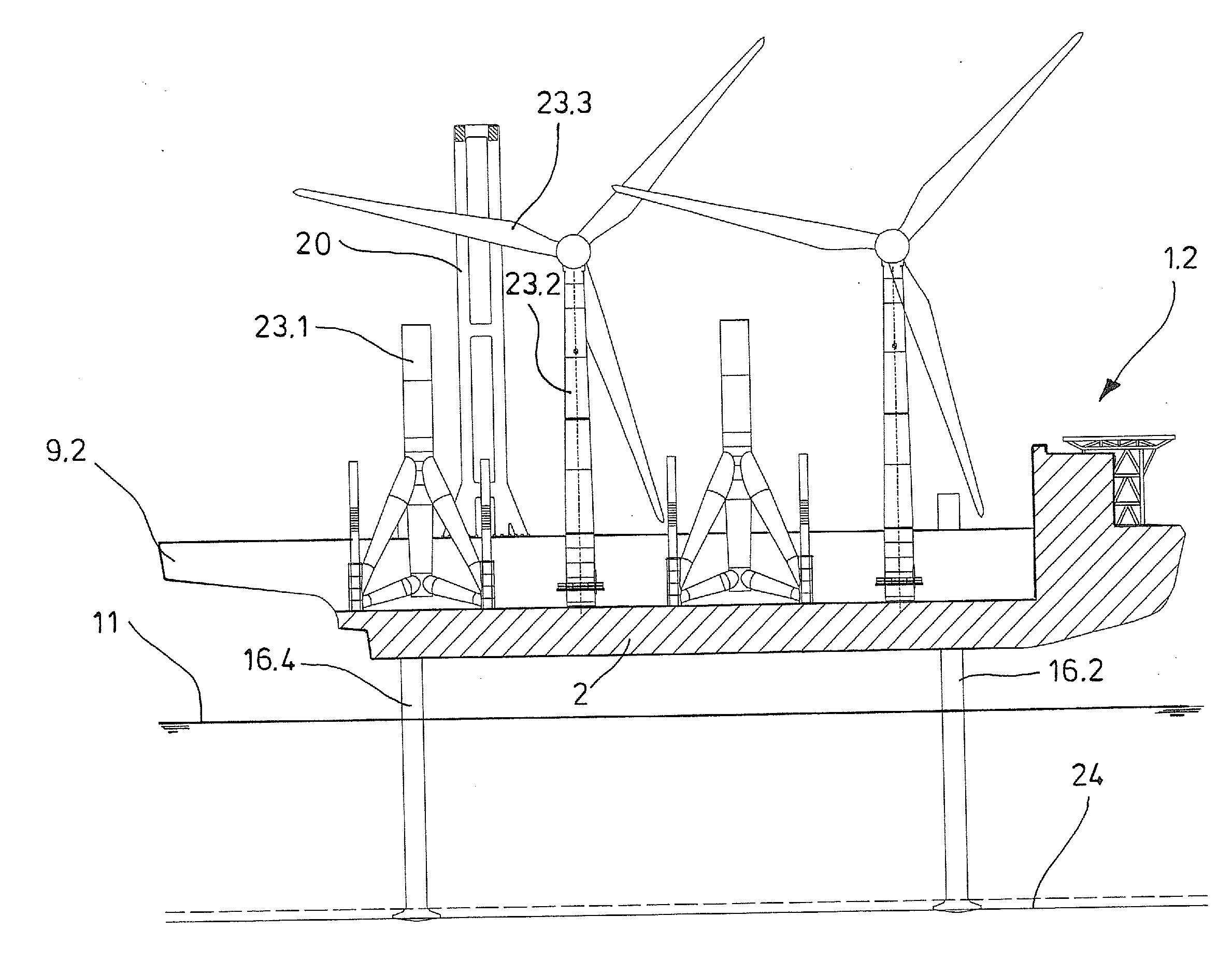
[0014]The U-shaped cross-section of the
hull is particularly advantageous for the strength of the ship. The ship is therefore particularly suitable for conveying heavy offshore structures. An additional
advantage for the hydrodynamics of the ship and the connection of the two structures is that the jack-up leg systems can be integrated in the side walls. When setting up offshore structures, the ship can be fixed to the ocean floor by lowering the jack-up legs. The ship is thereby held in a stable reference position that is independent of the swell and influences of the current and wind. This is advantageous for setting up wind turbines because the masts must be aligned precisely vertical. In addition, the U-cross section has the
advantage that the top edges of the side walls can be used as a base for the movable crane. Consequently, the crane can move above the offshore structures with which the ship is loaded. The ship preferably has a loading
deck on the top side of the floor to provide a high hold over which the crane can move. By means of the movable crane, offshore structures stored on the loading
deck can be picked up and transported to the projections. Between the projections, the offshore structures can be lowered and placed on the ocean floor since the hull does not have a loading
deck or respectively floor there. A plurality of offshore structures placed in a row in the longitudinal direction of the hull can be brought to the setup site in a single trip and set up sequentially. The ship is therefore particularly economical to use. The crane can transport the offshore structures vertically aligned because the load lifting
system of the crane can grasp the offshore structures at a high attachment point. In particular, the ship can transport and assemble masts and vertically aligned foundations of wind turbines. The wind
turbine does not have to be transported and set down as a unit with the mast mounted on the foundation. The cargo therefore does not extend as high from the hull of the ship as is the case in WO 2004 / 087494 A2, the entire contents of which is incorporated herein by reference; consequently, the ship has more options for use.
[0017]According to another embodiment, the crane is a portal crane that bears the crane bridge on supports movable on the top edges of the side walls. With the portal crane, the crane bridge is arranged particularly tall so that the ship can be used to convey and set up particularly tall offshore structures. According to another embodiment, the crane is a gantry screen. The crane bridge of the
gantry crane can be directly supported and moved on the top edges of the side walls. According to another embodiment, the crane bridge of the
gantry crane is movable on rails that are supported by supports on the top edges of the side walls. With this ship, the crane bridge is arranged particularly tall so that it can convey and to set up particularly tall offshore structures.
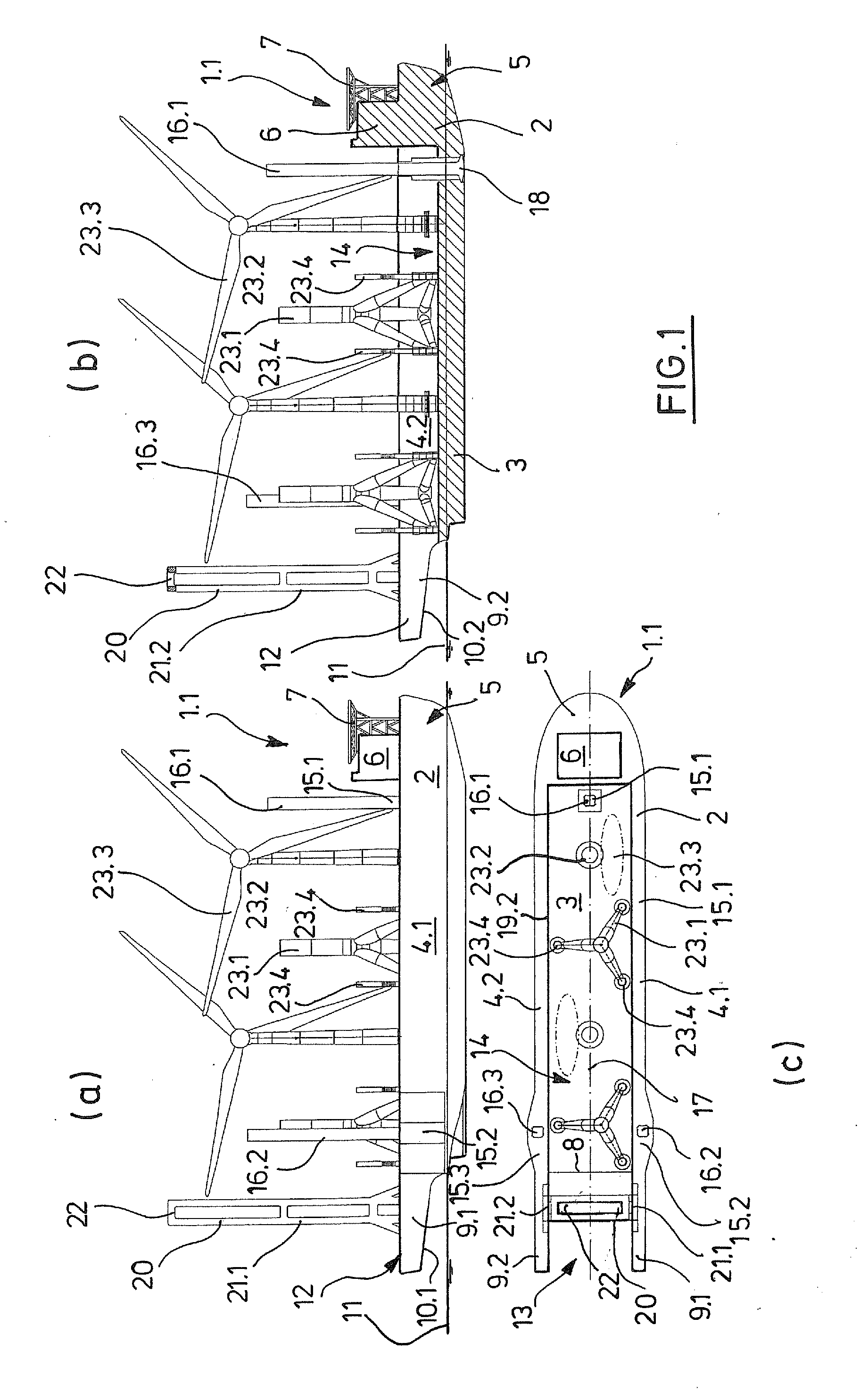
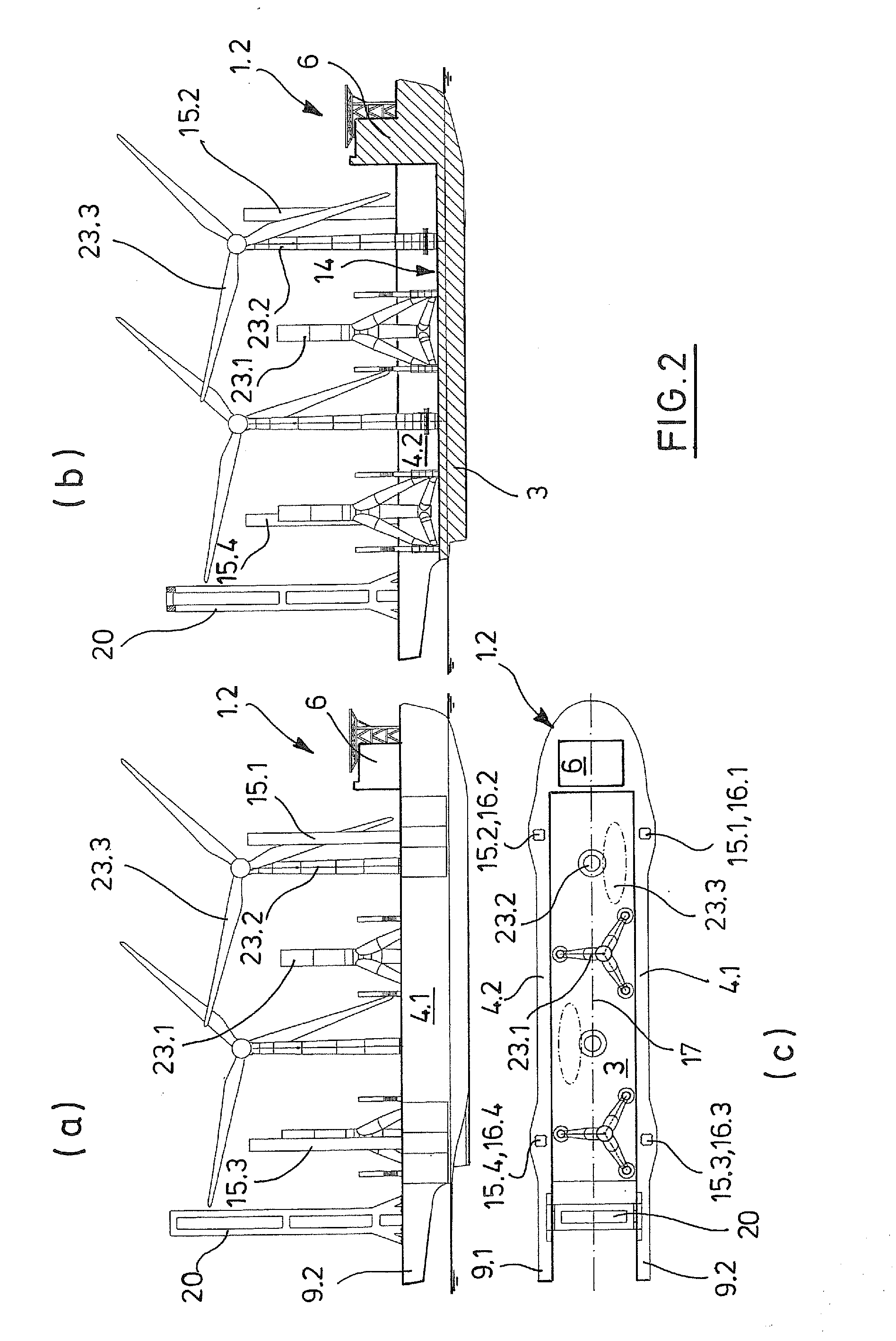
[0018]According to one embodiment, the side walls are
cut out at the bottom in the area of the projections so that the bottom edge of the overhangs is arranged above the water line of the hull while sailing. The
stern of the ship is therefore designed like a bracket so that the ship can sail with the hull above a
pier, and a transfer site for the offshore structures is arranged between the projections. Offshore structures placed on the transfer site can be picked up with the assistance of the crane arranged on the ship and set down on the ship. The ship can therefore pick up offshore structures in a harbor without using harbor cranes. Cargo in a harbor can therefore be picked up without using the jack-up legs. The ship is preferably fixed to the floor of the harbor when loading by lowering the jack-up legs.
[0023]It is to be understood that the ship has a propulsion
system. This can be designed in various ways. According to one embodiment, the ship has a marine
propeller drive and front and rear maneuvering aids. The marine
propeller drive in connection with the bow thrusters enables the ship to be precisely positioned at the setup site and in the harbor before it is fixed with the jack-up legs. Alternately, the ship's propulsion
system can comprise
rudder propellers by means of which the ship can be precisely maneuvered.
[0027]The ship can be equipped with offshore structures in various ways. According to one embodiment, the ship is either equipped homogeneously with a plurality of foundations or masts of wind turbines sequentially arranged in the direction of the ship's longitudinal axis, or heterogeneously, with alternating masts and foundations of wind turbines. When heterogeneously equipped, a foundation is preferably arranged next to the
stern of the ship since this has to be set down first, and then a mast is set on the foundation. The position of the ship does not have to be changed. It is also quite possible for the ship to be heterogeneously equipped with a group of masts followed by a group of foundations. After the foundations are set down, the masts can be attached to the set down foundations. At least one change of position is required to do this.
[0036]According to another embodiment, the ship is lifted with the jack-up legs with the hull at least partially out of the water. This increases the load on the jack-up legs and fixes the ship more securely to the ground. When the hull is lifted only partially out of the water with the jack-up legs, the
buoyancy acts on the hull. This relieves the jack-up leg systems so that they do not have to be as strongly dimensioned as is the case with a ship with a hull that can be completely lifted out of the water with the jack-up leg systems.

