Control method for stereolithography structure
- Summary
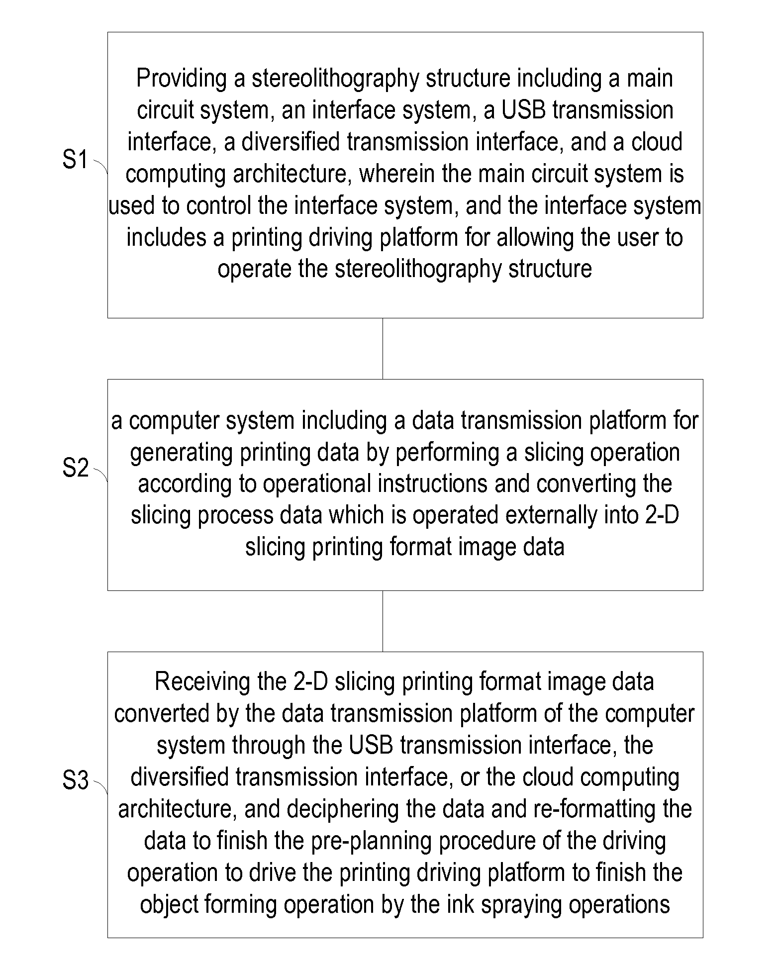
- Abstract
- Description
- Claims
- Application Information
AI Technical Summary
Benefits of technology
Problems solved by technology
Method used
Image

Examples
Embodiment Construction
[0030]An exemplary embodiment embodying the features and advantages of the invention will be expounded in following paragraphs of descriptions. It is to be realized that the present invention is allowed to have various modification in different respects, all of which are without departing from the scope of the present invention, and the description herein and the drawings are to be taken as illustrative in nature, but not to be taken as a confinement for the invention.
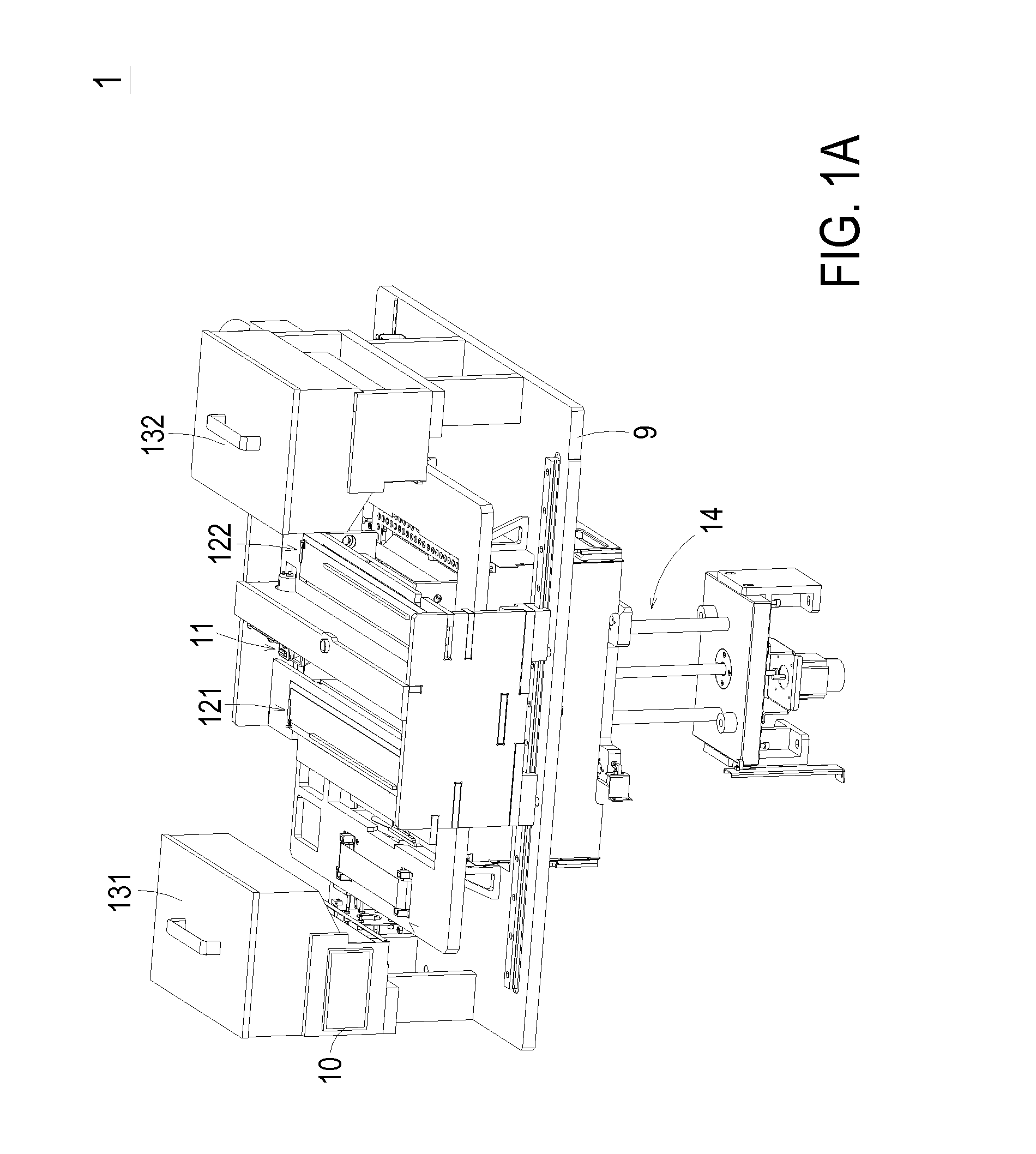
[0031]Referring to FIG. 1A, the 3-D view of the stereolithography structure according to an exemplary embodiment of the invention is shown. In FIG. 1A, the stereolithography structure 1 includes a constructive base9. The stereolithography structure 1 includes a touchscreen panel, a printing module 11, a plurality of toner storage tanks, a plurality of toner supply tanks, an elevator 14, and a constructive tank (not shown) mounted on the constructive base 9. The constructive tank includes a constructive platform and is ...
PUM
| Property | Measurement | Unit |
|---|---|---|
| Linear resolution | aaaaa | aaaaa |
| Angle | aaaaa | aaaaa |
| Color | aaaaa | aaaaa |
Abstract
Description
Claims
Application Information
 - R&D
- Intellectual Property
- Life Sciences
- Materials
- Tech Scout
- Unparalleled Data Quality
- Higher Quality Content
- 60% Fewer Hallucinations
Browse by: Latest US Patents, China's latest patents, Technical Efficacy Thesaurus, Application Domain, Technology Topic, Popular Technical Reports.
© 2025 PatSnap. All rights reserved.Legal|Privacy policy|Modern Slavery Act Transparency Statement|Sitemap|About US| Contact US: help@patsnap.com