Milling tool, and milling insert kit

a technology of insert kits and milling tools, which is applied in the field of milling tools, can solve the problems of manufacturing technical limitations of the size of milling inserts that can be manufactured, and achieve the effects of improving the overall economy of the milling tool, reducing the cost of manufacturing, and high accuracy

Inactive Publication Date: 2012-10-11
SANDVIK INTELLECTUAL PROPERTY AB
View PDF12 Cites 13 Cited by
  • Summary
  • Abstract
  • Description
  • Claims
  • Application Information

AI Technical Summary

Benefits of technology

[0021]According to an additional embodiment of the invention, the outer seats comprise an inner abutment surface, which extends upward from the support surface and against which the outer milling inserts abut. By such an abutment surface, the position of the outer milling inserts in the radial direction in respect of the rotation axis can be guaranteed with high accuracy. Advantageously, the outer milling insert may be fastened in the seat by a wedge-shaped body corresponding to the one utilized for the inner milling insert. It is, however, also possible to provide the outer milling insert with a fastening hole that extends through the upper side and the under side, wherein the outer milling insert may be fastened in the seat by means of a fixing screw that extends through the fastening hole into a threaded hole that extends through the support surface into the tool body.
[0022]According to another embodiment of the invention, each outer milling insert is indexable by rotation around said axis, which forms a centre axis, between two opposite insert positions and comprises a first set, having a primary main cutting edge and a secondary main cutting edge for a first insert position, and a second set, having a primary main cutting edge and a secondary main cutting edge for a second insert position. In such a manner, the service life of the outer milling inserts can be extended and thereby the total economy for the milling tool can be further improved. Advantageously, the outer milling insert according to this embodiment may be fastened by means of a fixing screw that extends through a fastening hole in the tool body in the way explained above. In this case, the fastening hole forms a centre hole that is concentric with the centre axis.

Problems solved by technology

A problem of the previously known milling tools is the difficulty of manufacturing milling inserts that have such a size that they are suitable for the production of workpieces having large or deep gashes, or workpieces having great cogs, for instance greater than Mn=6.
There are manufacturing technical limitations for how large milling inserts that can be manufactured by sintering of milling inserts of cemented carbide.
Today, available moulding machines only manage milling inserts of a limited size.

Method used


Image

  • Milling tool, and milling insert kit
  • Milling tool, and milling insert kit
  • Milling tool, and milling insert kit

Examples


first embodiment

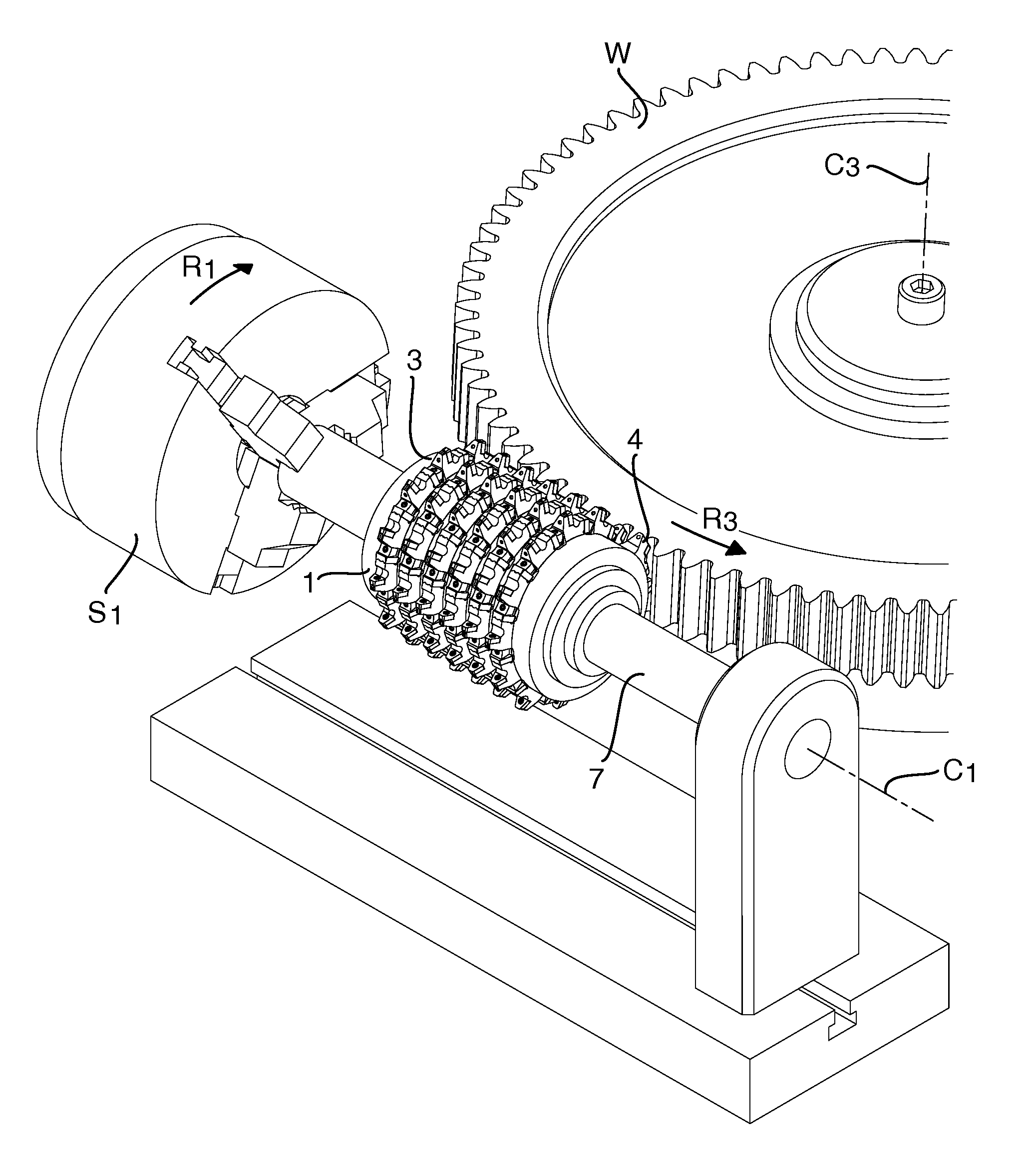
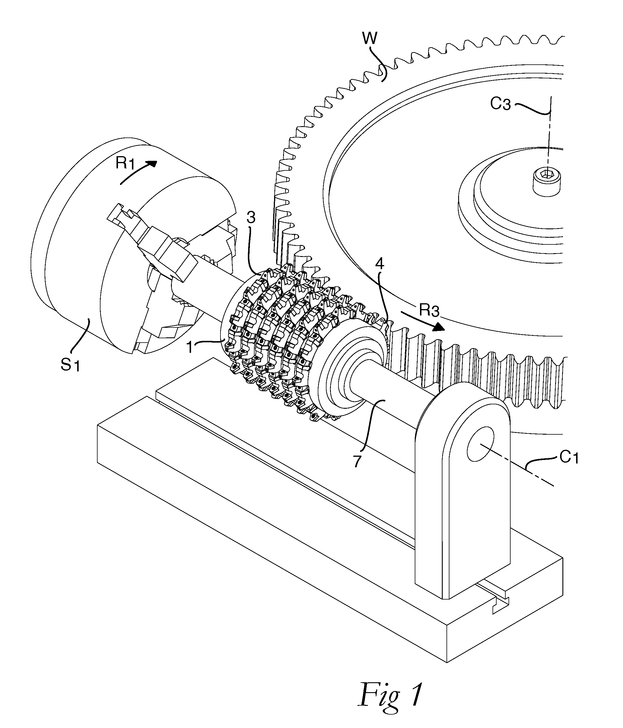
[0044]FIG. 1 shows schematically a machine tool including a milling tool that is formed for gear cutting and more precisely for so-called hobbing of a workpiece W having cogs. The milling tool is suitable for the cutting machining of different workpieces W, such as gear wheels, racks, splines, impellers for hydraulic pumps, and similar cogged elements.

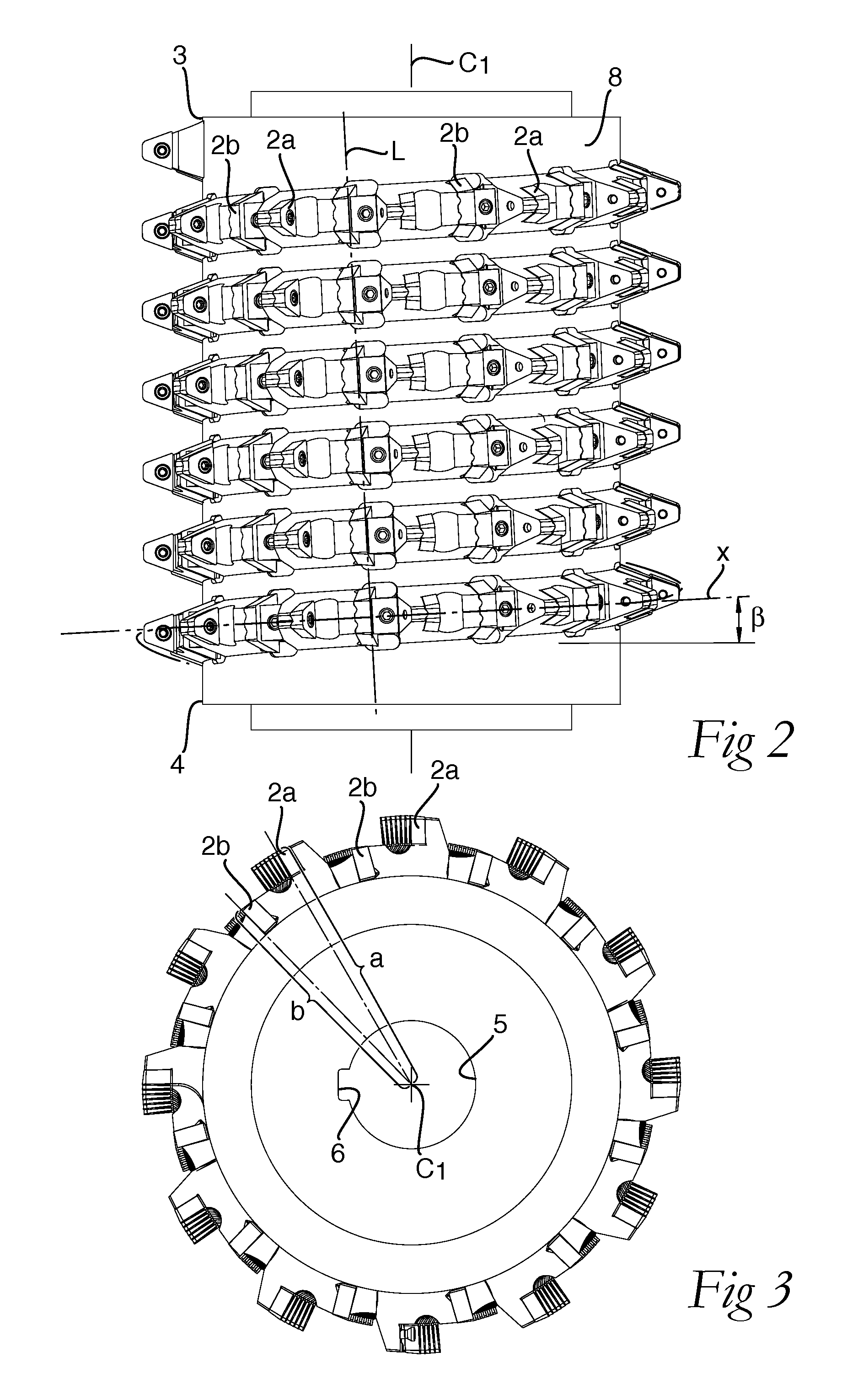
[0045]A first embodiment of the milling tool is shown in FIGS. 2-4. The milling tool comprises a tool body 1, which may be manufactured from steel, and a large number of replaceable milling inserts 2a, 2b, which may be manufactured from a material that is harder than steel, for instance cemented carbide. The tool body 1 defines a rotation axis C1 and has a first end 3 and an opposite second end 4. The rotation axis C1 extends through the first end 3 and the second end 4.

[0046]The milling tool also comprises a through axial hole 5, see FIG. 3, having a straight groove 6 for the receipt of a rod 7, for instance in accordance with DIN 138...

second embodiment

[0070]In the second embodiment, the outer seats 9a lack an inner abutment surface but instead comprise an axial elongate ridge 37 of the support surface 10. The outer milling insert 2a has two corresponding elongate valleys 38 that extend from the under side 21, see particularly FIG. 10c. When the outer milling insert 2a is mounted in the outer seat 9a, the axial elongate ridge 37 will be in engagement with the elongate valley 38 of the under side 21 of the outer milling insert 2an so that the radial position of the outer milling insert 2a in respect of the rotation axis C1 is guaranteed. The axial elongate ridge 37 has, as the ridge 14, two leaning flank surfaces that extend between the support surface 10 and an upper surface of the radial elongate ridge 37. The two flank surfaces form an obtuse angle with each other. This angle may be 90-140°, for instance 120°. The upper surface may be plane and parallel to the support surface 10. Each one of the elongate valleys 38 has, as the e...

third embodiment

[0073]An additional difference between the first and third embodiment is that, in the latter, the outer milling insert 2a lacks fastening hole and instead is fastened in the outer seat 9a by means of a wedge-shaped block 44 that abuts against the upper side 22 of the outer milling insert 2an and presses the outer milling insert 2a against the support surface 10 and the two elongate ridges 14 and 41. The wedge-shaped block 44 is clamped against the outer milling insert 2a by means of a double-threaded screw 45 that extends through and is in engagement with the wedge-shaped block 44 and into a threaded hole 46 in the tool body 1.

[0074]In the third embodiment, the inner seat 9b and the inner milling insert 2b are formed in the same way as in the second embodiment.

[0075]In a fourth embodiment the succession line x extends around the C1 in a plane being perpendicular to the rotation axis C1, i.e. the pitch is zero. Such a milling tool is suitable milling of gashes or slots or other groov...


PUM

PropertyMeasurementUnit
pressure angleaaaaaaaaaa
lengthaaaaaaaaaa
lengthaaaaaaaaaa

Abstract

Milling tool and milling insert kit are provided for the gash milling of a workpiece. The tool comprises a tool body that defines a rotation axis and has a first end, an opposite second end, and a peripheral surface that extends around the rotation axis between the first end and the second end. A large number of separated seats, which are arranged one after the other in the tool body along a line and receive one each of corresponding number of replaceable milling inserts, comprise a primary main cutting edge and a secondary main cutting edge that converge to each other. The milling inserts comprise outer milling inserts, which project from the tool body by a first length from the rotation axis, and inner milling inserts, which project from the tool body by a second length from the rotation axis. The first length is considerably greater than the second length.

Description

RELATED APPLICATION DATA[0001]This application is based on and claims priority under 37 U.S.C. §119 to Swedish Application No. 1150309-1, filed 8 Apr. 2011, the entire contents of which are incorporated herein by reference.FIELD OF THE INVENTION[0002]The present invention relates to a milling tool for gash milling, such as groove milling, slotting, gear milling, in particular so-called hobbing, etc. More particularly, the invention relates to a milling tool according to the preamble of claim 1, see U.S. Pat. No. 5,593,254, and to a milling insert kit according to the preamble of claim 17.[0003]It is known to manufacture gear milling tools having fixed milling inserts that are formed by cutting machining of the tool body. This invention relates to a milling tool wherein the milling inserts instead are formed of a plurality of replaceable milling inserts that are arranged one after the other along a succession line that extends around the tool body.BACKGROUND OF THE INVENTION AND PRIO...

Claims


Application Information

Patent Timeline
Patent Type & Authority Applications(United States)
IPC IPC(8): B23C5/20B23F21/12
CPCB23F21/166Y10T407/1725Y10T407/23Y10T407/1745Y10T407/1715Y10T407/1942B23F21/126B23F21/163
Inventor STURE, SJOO
Owner SANDVIK INTELLECTUAL PROPERTY AB
Why Eureka
Try Eureka