Microfluidic platform for synthetic biology applications

Active Publication Date: 2012-10-11
RGT UNIV OF CALIFORNIA +1
View PDF4 Cites 73 Cited by
  • Summary
  • Abstract
  • Description
  • Claims
  • Application Information

AI Technical Summary

Benefits of technology

[0010]When describing assembly strategies/methods the t

Problems solved by technology

This can lead to a large combinatorial problem where several thousands of combinations of parts have to be assembled.
The sc

Method used


Image

  • Microfluidic platform for synthetic biology applications
  • Microfluidic platform for synthetic biology applications
  • Microfluidic platform for synthetic biology applications

Examples


example 1

SynBioChip Microfluidic Platform

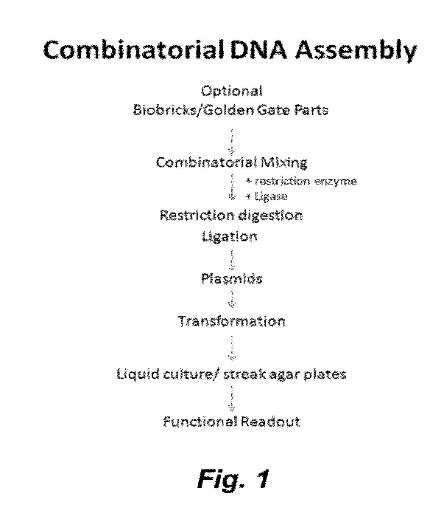
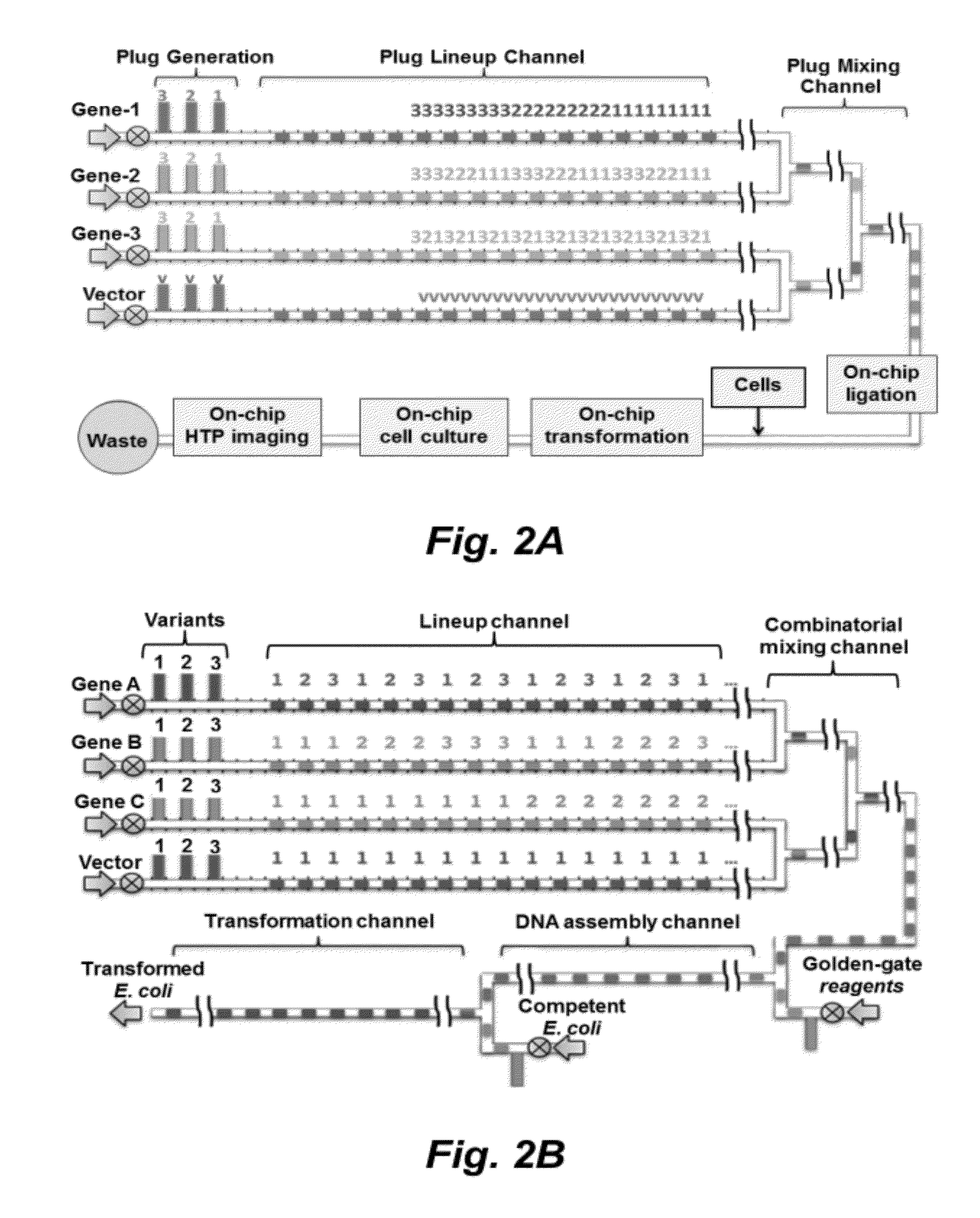
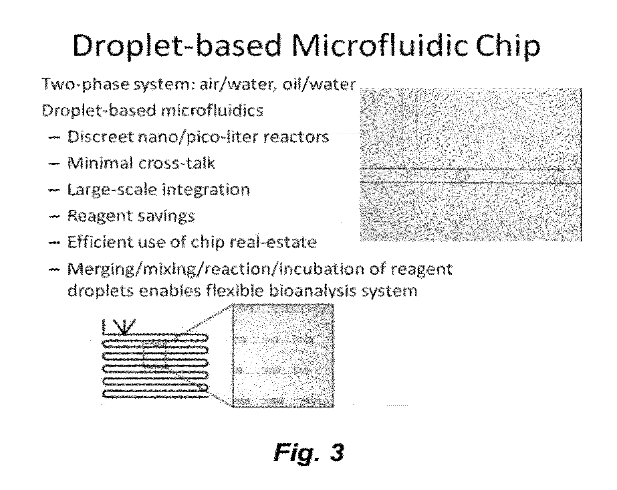
[0179]The heat of the integrated system(s) described herein is a microfluidic chip that enables thousands of reactions in parallel using nL droplets as reaction vessels. Droplets are created by dispensing aqueous solution carrying biological parts into an oil stream. The chip allows on-demand creation and merger of droplets to permit assembly of DNA into plasmids, transformation of cells, culture of transformed cells, and subsequent phenotype screening. FIG. 39A shows a schematic of the operations performed in a SynBioChip and FIG. 39B shows a drawing of the chip.

[0180]Chip Fabrication.

[0181]Chips are fabricated by standard photolithography process described in many of our publications (see, e.g., Throckmorton (2002) Anal. Chem., 74: 784-789). To allow for structural rigidity while keeping the ability to easily clean the chip for reuse and macroscopic analysis, a thin PDMS layer sandwiched by two quartz wafers can be utilized. The bottom wafer contain...


PUM

PropertyMeasurementUnit
Temperatureaaaaaaaaaa
Flow rateaaaaaaaaaa

Abstract

This invention provides methods and compositions for assembling biological constructs (e.g., plasmids, transformed cells, etc.). In certain embodiments the methods involve encapsulating separate components of said biological construct each in a fluid droplet confined in a fluid channel; optionally mixing droplets from different fluid channels to for a sequenced order of droplets carrying different components of said biological construct in a channel or chamber; and optionally combining two or more droplets each containing different components of said biological construct to permit said components to react with each other in one or more reactions contributing to the assembly of said biological construct.

Description

CROSS-REFERENCE TO RELATED APPLICATIONS[0001]This application claims benefit of and priority to U.S. Ser. No. 61 / 471,027, filed on Apr. 1, 2011, which is incorporated herein by reference in its entirety for all purposes.STATEMENT OF GOVERNMENTAL SUPPORT[0002]This invention was made with government support under Contract No. DE-AC02-05CH11231 awarded by the U.S. Department of Energy. The government has certain rights in this invention.FIELD OF THE INVENTION[0003]The present invention relates to synthetic biology and microfluidics. In certain embodiments microfluidic devices and methods are provided for the synthesis of biological constructs including, but not limited to plasmids, and transformed cells.BACKGROUND OF THE INVENTION[0004]Synthetic biology applications often involve assembly of several biological parts (e.g., genes) in a plasmid. This can lead to a large combinatorial problem where several thousands of combinations of parts have to be assembled. The scale of the problem i...

Claims


Application Information

Patent Timeline
IPC IPC(8): C12P19/34C12N15/63C12M1/00C12N15/82C12Q1/04C12M1/40C12N11/00C12N15/85
CPCC12N15/10C12N15/66C12N15/1027
Inventor CHANG, CHIEHBHARADWAJ, RAJIVSINGH, ANUP K.CHANDRASEKARAN, AARTHIHILLSON, NATHAN J.
Owner RGT UNIV OF CALIFORNIA
Why Eureka
Try Eureka