Endoscopic diagnosis system

a diagnosis system and endoscope technology, applied in the field of endoscope diagnosis system, can solve the problems of difficult comparison, difficult distinction between normal region and lesion, and the position of the lesion cannot be aligned among the three autofluorescence images, and achieve the effect of accurate distinction of the lesion and high contras

Inactive Publication Date: 2012-10-11
FUJIFILM CORP
View PDF12 Cites 5 Cited by
  • Summary
  • Abstract
  • Description
  • Claims
  • Application Information

AI Technical Summary

Benefits of technology

[0011]Thus, an object of the present invention is to provide an endoscopic diagnosis system enabling acquisition of autofluorescence images with no misalignment between the autofluorescence images permitting an accurate recognition of a lesion.
[0026]According to the present invention, a plurality of excitation light having different wavelengths are emitted for simultaneous illumination, and the autofluorescence emitted from an autofluorescent substance is dispersed by color filters to acquire a first and a second autofluorescence image. Therefore, no misalignment occurs between the first and the second autofluorescence image, and the difference between normal region and lesion can be displayed with a high contrast, enabling an accurate distinction of a lesion. Another advantage is that no excitation light cut filer is required.

Problems solved by technology

However, because the illumination timing differs among the three excitation light according to the method described in JP 2008-43383 A, the positions of the lesion fail to align among the three autofluorescence images even when the three fluorescence images are displayed simultaneously.
In addition, three fluorescence images must be visually compared to determine the lesion, thus making the comparison difficult.
According to this method, however, distinction between normal region and lesion is difficult where, when NADH and elastin both emit fluorescence, the fluorescence intensity does not change in concordance between normal region and lesion.

Method used


Image

  • Endoscopic diagnosis system
  • Endoscopic diagnosis system
  • Endoscopic diagnosis system

Examples


Embodiment Construction

[0041]The endoscopic diagnosis system according to the present invention will be described below in detail based on the preferred embodiments illustrated in the attached drawings.

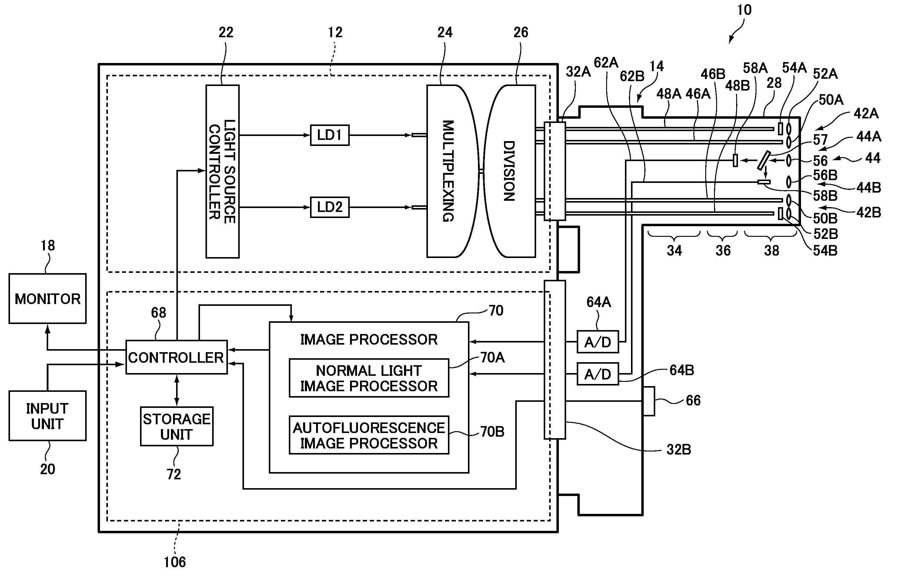
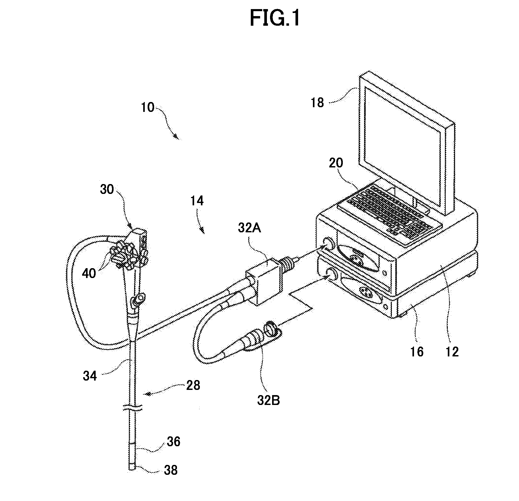
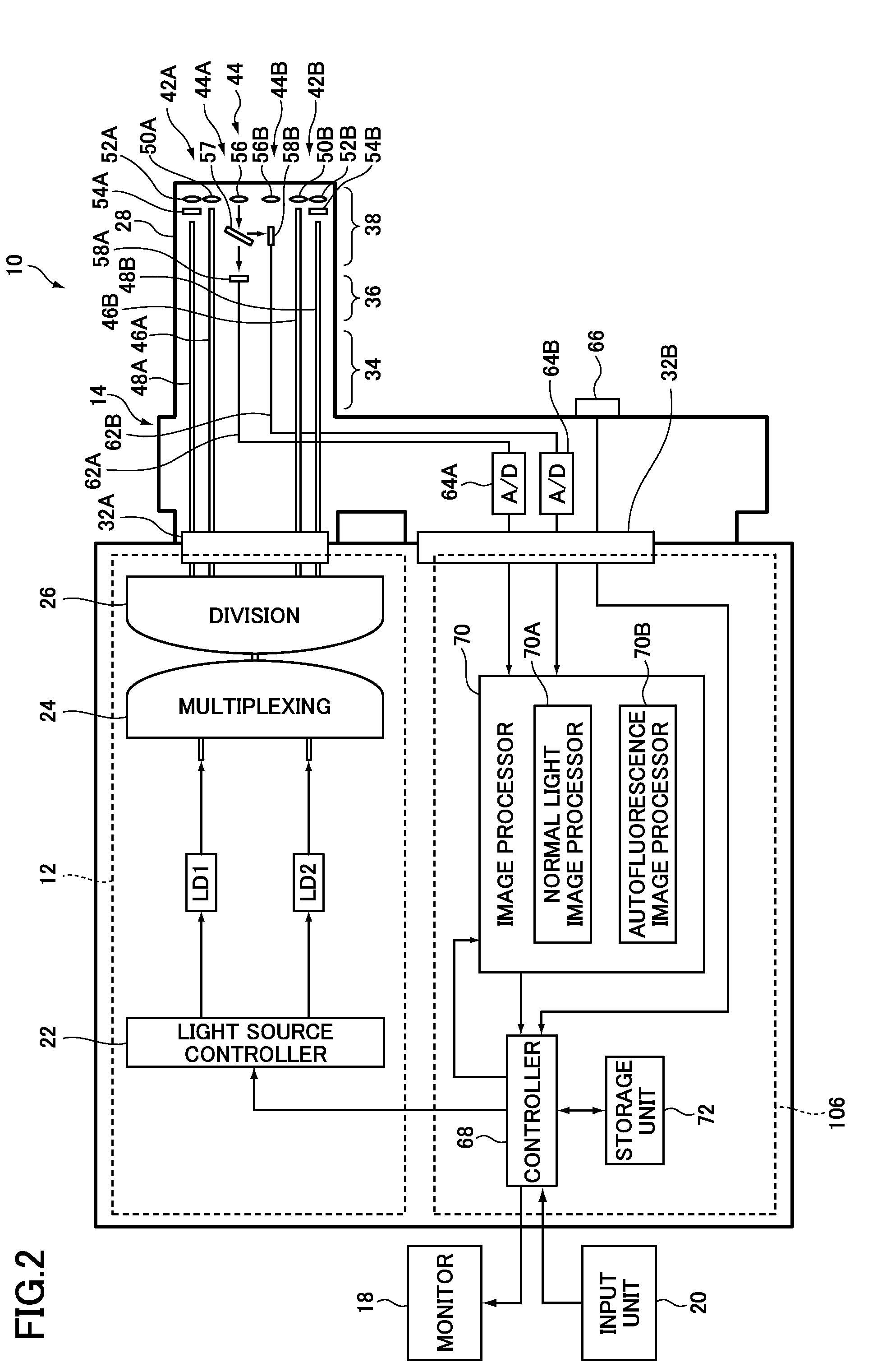
[0042]FIG. 1 is an external view of an embodiment illustrating a configuration of the endoscopic diagnosis system according to the invention; FIG. 2 is a block diagram illustrating an internal configuration thereof. An endoscopic diagnosis system 10 illustrated in these drawings comprises a light source device 12 for emitting a plurality of light having different ranges of wavelength; an endoscope device 14 for guiding light emitted from the light source device 12 to illuminate a subject's region under observation and image the reflected light or an autofluorescence from the subject; a processor 16 for image-processing the image acquired by the endoscope device 14 and outputting an endoscopic image; a monitor 18 for displaying the endoscopic image outputted from the processor 16; and an input unit 20 for re...


PUM


Abstract

An endoscopic diagnosis system includes a light source for simultaneously emitting at least two excitation light having different central wavelengths for exciting at least two autofluorescent substances to generate autofluorescence containing first autofluorescence whose intensity is strong in a lesion and weak in a normal region and second autofluorescence whose intensity is strong in a normal region and weak in a lesion, color filters having spectral transmission characteristics that block the excitation light and transmit the autofluorescence, image sensor for imaging autofluorescence generated from first and second autofluorescent substances contained in a subject's region under observation and dispersed by color filters to acquire first and second autofluorescence images as the at least two excitation light illuminate the region under observation, and an image sensor for image-processing and displaying the first and second fluorescence images.

Description

BACKGROUND OF THE INVENTION[0001]The present invention relates to an endoscopic diagnosis system that images the autofluorescence emitted from autofluorescent substances contained in a subject's region under observation (organism) and obtains autofluorescence images.[0002]There are conventionally used endoscope devices wherein normal light (white light) emitted from a light source device is guided to the tip of an endoscope to illuminate a subject's region under observation, and the reflected light is imaged to acquire a normal light image (white light image) for normal light observation (white light observation). In recent years, there have been used endoscope devices whereby a subject's region under observation is illuminated by excitation light for autofluorescence observation (special light), and the autofluorescence emitted from an autofluorescent substance is imaged to acquire an autofluorescence image (special light image) in order to perform autofluorescence observation (spe...

Claims


Application Information

Patent Timeline
Patent Type & Authority Applications(United States)
IPC IPC(8): A61B1/06A61B1/04
CPCA61B1/00186A61B1/043A61B1/0638A61B1/0653A61B5/14556A61B5/1459A61B1/063A61B5/0071
Inventor YAMAMOTO, HIROAKI
Owner FUJIFILM CORP
Why Eureka
Try Eureka