Thermosyphon Heat Recovery

a heat recovery and thermosyphon technology, applied in the field of heat recovery units, can solve the problems of limited heat exchange, uncontrollable fluid heat generation, and generating steam or water that is too hot for use, and achieve the effect of optimizing heat transfer and efficiently transferring hea

Active Publication Date: 2012-10-18
OLIVE TREE PATENTS 1
View PDF4 Cites 12 Cited by
  • Summary
  • Abstract
  • Description
  • Claims
  • Application Information

AI Technical Summary

Benefits of technology

[0024]The apparatus of the invention is particularly designed to be easily fitted to a conventional hot water heater. Specifically, the apparatus of the invention (the heat exchanger) comprises a tube-on-tube heat exchanger which is configured to be wound counterclockwise upward (north of equator applications, and clockwise upward for south of the equator applications) in a relatively tight diameter (6″) to provide for good refrigerant turbulence, clipped in solder for heat transfer, of a tubing size designed to minimize friction related pressure loss, then placed in a cabinet of adequate size to contain said heat exchanger to be located optimally in relation to the water outlet from the hot water storage tank and the heated water inlet to the hot water tank. The input of the secondary fluid conduit of the heat exchanger is then easily fitted to the existing hose bib (bottom cold water outlet of the water storage tank)by means of a flexible water heater hose of an inside diameter of a size designed to minimize friction loss and maximize fluid flow and the output of the fluid conduit of the secondary fluid of the heat exchanger is then easily fitted with a hot water rated hose of an inside diameter size designed to minimize friction loss and maximize fluid flow from the outlet of the heat exchanger to a new boiler drain attached by means of an anti-siphon tee to the hot water discharge line of the water heater at the top of the tank. The apparatus further includes an anti-scald valve assembly which is easily incorporated within the cold and hot water supply lines to the tank. The anti-scald valve assembly limits the temperature of the heated water being discharged from the tank via the hot water supply line.

Problems solved by technology

In some, the water flows through a heat exchanger thermosyphonically, but with limited heat exchange due to inadequate consideration of the requirements for optimized heat transfer and efficient fluid flow.
A major disadvantage to the former types of precoolers is their tendency to uncontrollably heat the fluid and, in the case of water, may produce steam or water that is too hot for use.
This necessarily precludes efficient production of hot fluid, in that some energy must be expended to drive the pump mechanism, and some production of heat is lost due to pump controls, limiting operation time of the pump.

Method used


Image

  • Thermosyphon Heat Recovery
  • Thermosyphon Heat Recovery
  • Thermosyphon Heat Recovery

Examples


Embodiment Construction

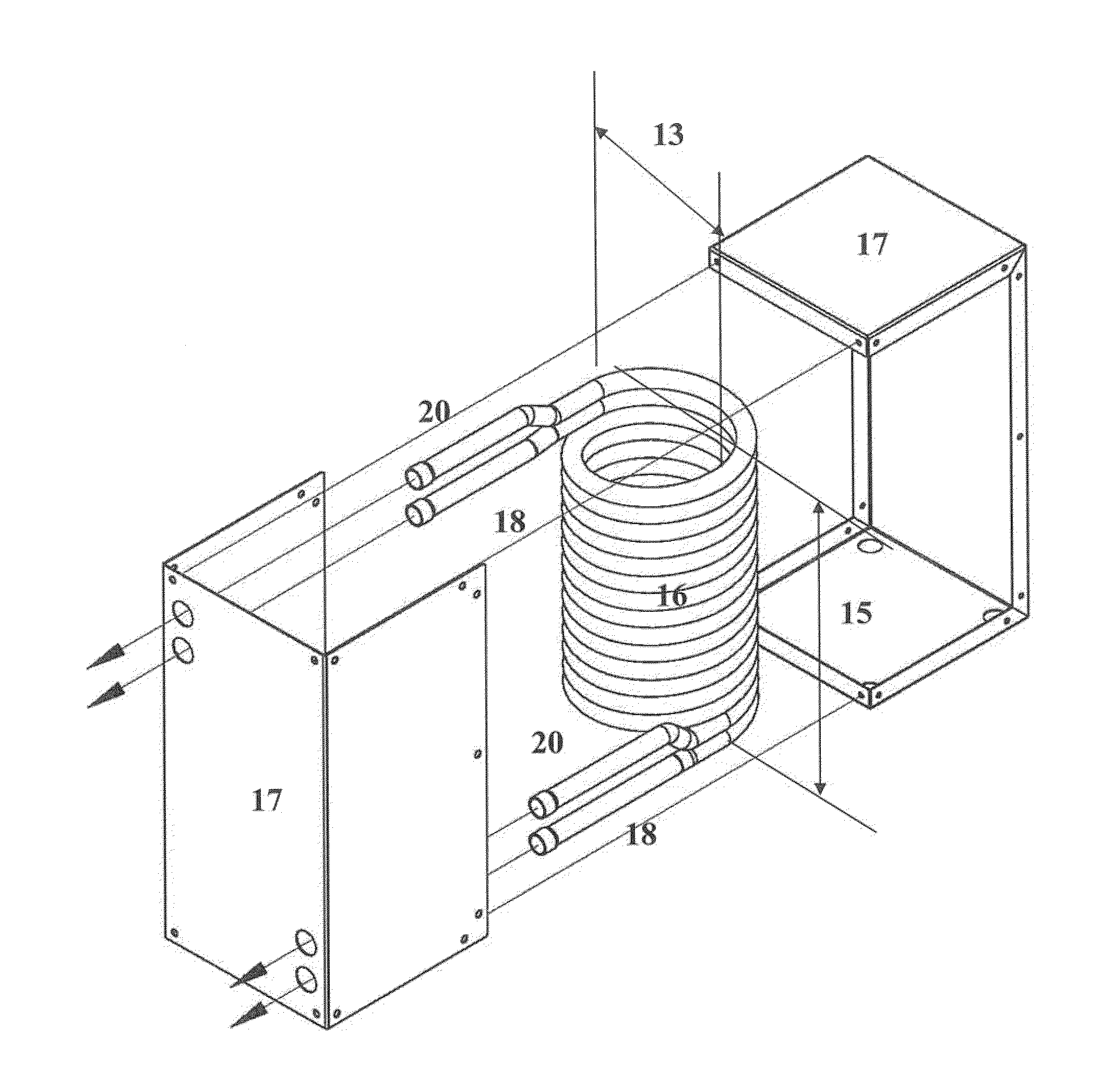
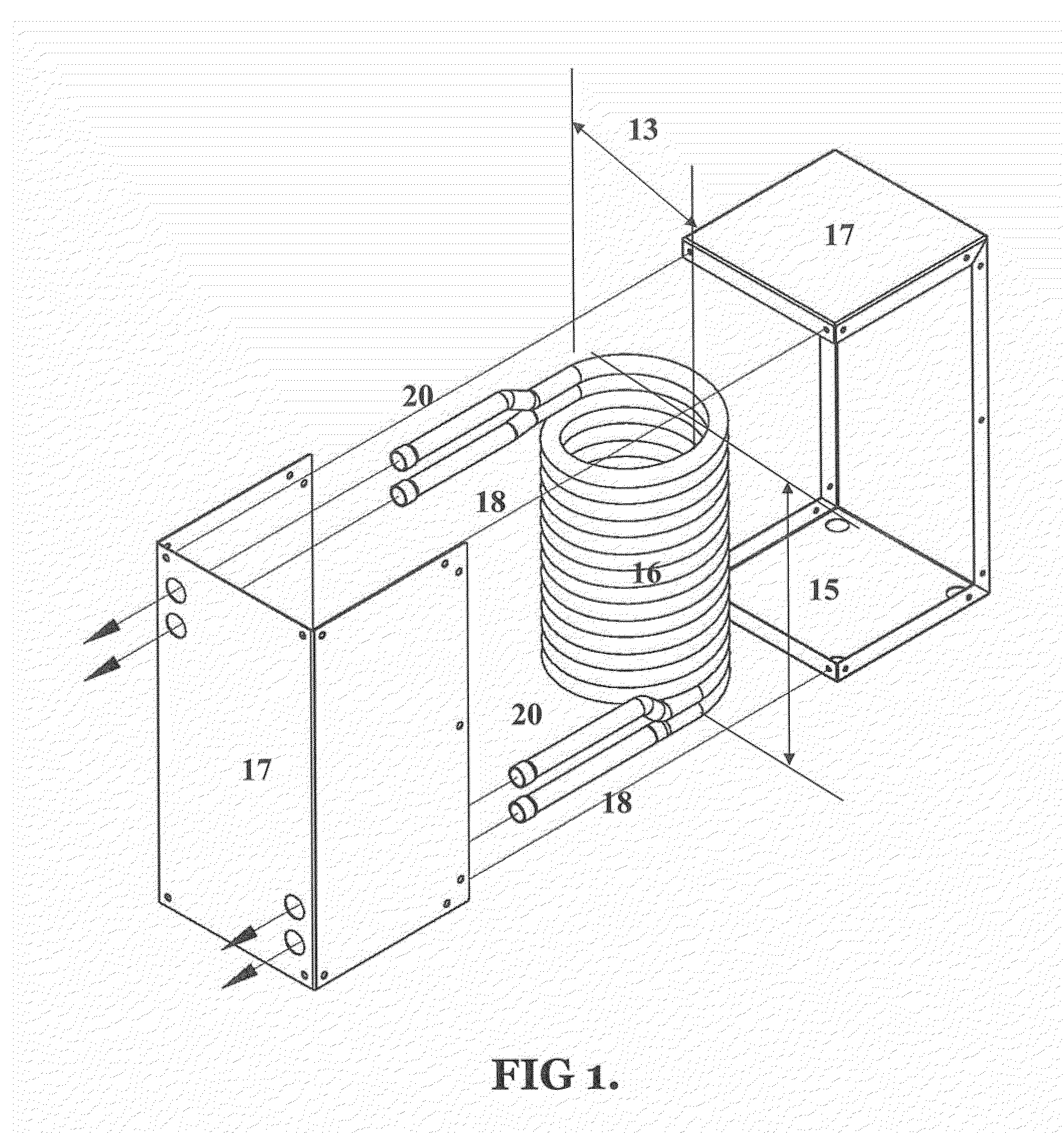
[0036]FIG. 1 is a schematic representation generally illustrating the structure and composition of the apparatus only of the heat exchanger and cabinet of the invention. The apparatus of the heat exchanger (16) comprises a first conduit (18) through which the first fluid (refrigerant) flows in heat exchange relationship with a second conduit (20) through which the second fluid flows. The first conduit (18) and the second conduit (20) are both sized based on the maximum HVACR tonnage or capacity intended for application to the heat exchanger for a maximum allowable friction related pressure drop of 4 psi for the total length of conduit through the heat exchanger. The heat exchanger is wound in a tight spiral at the minimum possible diameter (13) possible for manufacture, to maximize turbulence in the fluid flow. The total length of the heat exchanger conduits (15) is based on that diameter and the maximum allowable height of the heat exchanger based on considerations of possible wate...


PUM

PropertyMeasurementUnit
pressure dropaaaaaaaaaa
thicknessaaaaaaaaaa
thicknessaaaaaaaaaa

Abstract

A thermosyphonic heat recovery unit for thermosyphonic heat transfer of heat from a hotter first fluid to a cooler second fluid comprising a heat exchanger including a first fluid conduit and a second fluid conduit, optimized means for connecting fluids to the two conduits to optimize heat transfer and fluid flow, a pressurized cold fluid input and hot fluid output, whereby the second fluid thermosyphonically flows through said second conduit as the first fluid flows through said first conduit. Said system having an optimized heat exchanger tube-on tube spirally wound, with wind direction to take advantage of the Coriolus force effect, for optimized refrigerant and other fluid turbulence and therefore optimized heat transfer, and optimum location of said heat exchanger and sizes of connecting tubes to minimize refrigerant friction related pressure loss, and to optimize heat transfer, refrigerant flow and thermosyphonic second fluid flow through said heat exchanger.

Description

CROSS-REFERENCE TO RELATED INVENTIONS[0001]This application claims the benefit of provisional application number 61 / 453,561, filed Mar. 17, 2011, the disclosure of which is hereby incorporated by reference herein.BACKGROUND OF THE INVENTION[0002]1. Field of the Invention[0003]This invention relates to heat recovery units. More particularly, this invention relates to heat recovery units that operate thermosyphonically to flow water in a heat exchanging relationship with a source of heat.[0004]2. Description of the Prior Art[0005]Presently there exist many types of heat recovery units designed to operate in combination with a vapor compression heat transfer system such as a heat pump or air conditioner. Basically, heat recovery units operate as a precooler to desuperheat the hot refrigerant gas being discharged by the compressor of the system, and transfer such heat to a fluid such as water. In some applications, the precooler heat exchanger is positioned within a large tank such that...

Claims


Application Information

Patent Timeline
Patent Type & Authority Applications(United States)
IPC IPC(8): F28D15/00B21D53/02
CPCF28D15/00F28D7/0016F28D7/022F28D20/0039Y02B30/52Y10T29/4935F24H4/04F24H9/142F24H9/2007F24D19/1054F24D17/02
Inventor HEBERT, THOMAS H.
Owner OLIVE TREE PATENTS 1
Why Eureka
Try Eureka