Air gap control systems and methods

a control system and air gap technology, applied in the direction of dynamo-electric converter control, motor/generator/converter stopper, magnetic circuit shape/form/construction, etc., can solve the problems of affecting the operation of the control system

Active Publication Date: 2012-10-18
BWP GRP
View PDF1 Cites 46 Cited by
  • Summary
  • Abstract
  • Description
  • Claims
  • Application Information

AI Technical Summary

Benefits of technology

[0006]In one embodiment, an apparatus includes a first member that supports a magnetic flux carrying member and a second member that supports a magnetic flux generating member. The second member is disposed for movement relative to the first member. An air gap control system that includes an air gap control device is coupled to at least one of the first member or the second member. The air gap control system is configured to exert a force on one of the first member and the second member in response to movement of the other of the first member and the second member in a direction that reduces a distance between the first member and the second member to one of maintain a minimum distance between the first member and the second member and substantially center the one of the first member and the second member within a region defined by the other of the first member and the second member. The air gap control device is separate from a primary magnetic flux circuit formed between the first member and the second member.

Problems solved by technology

Significant violations of air gap size, such as where the air gap is nearly closed or is closed altogether, can be dangerous or destructive to equipment and personnel, particularly if the air gap is compromised during operation of the electromagnetic machine.
As the size of an electromagnetic machine increases, dependence on structural stiffness to ensure that a minimum air gap clearance is maintained can become impractical due to the weight and cost of the required structure.

Method used


Image

  • Air gap control systems and methods
  • Air gap control systems and methods
  • Air gap control systems and methods

Examples


Embodiment Construction

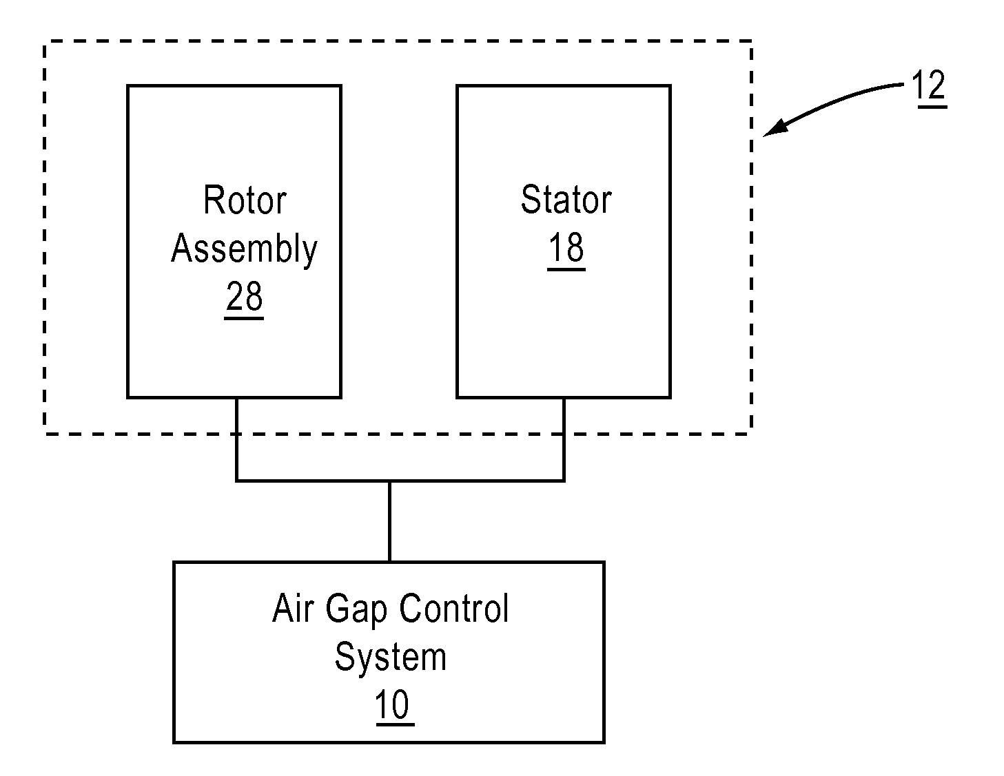
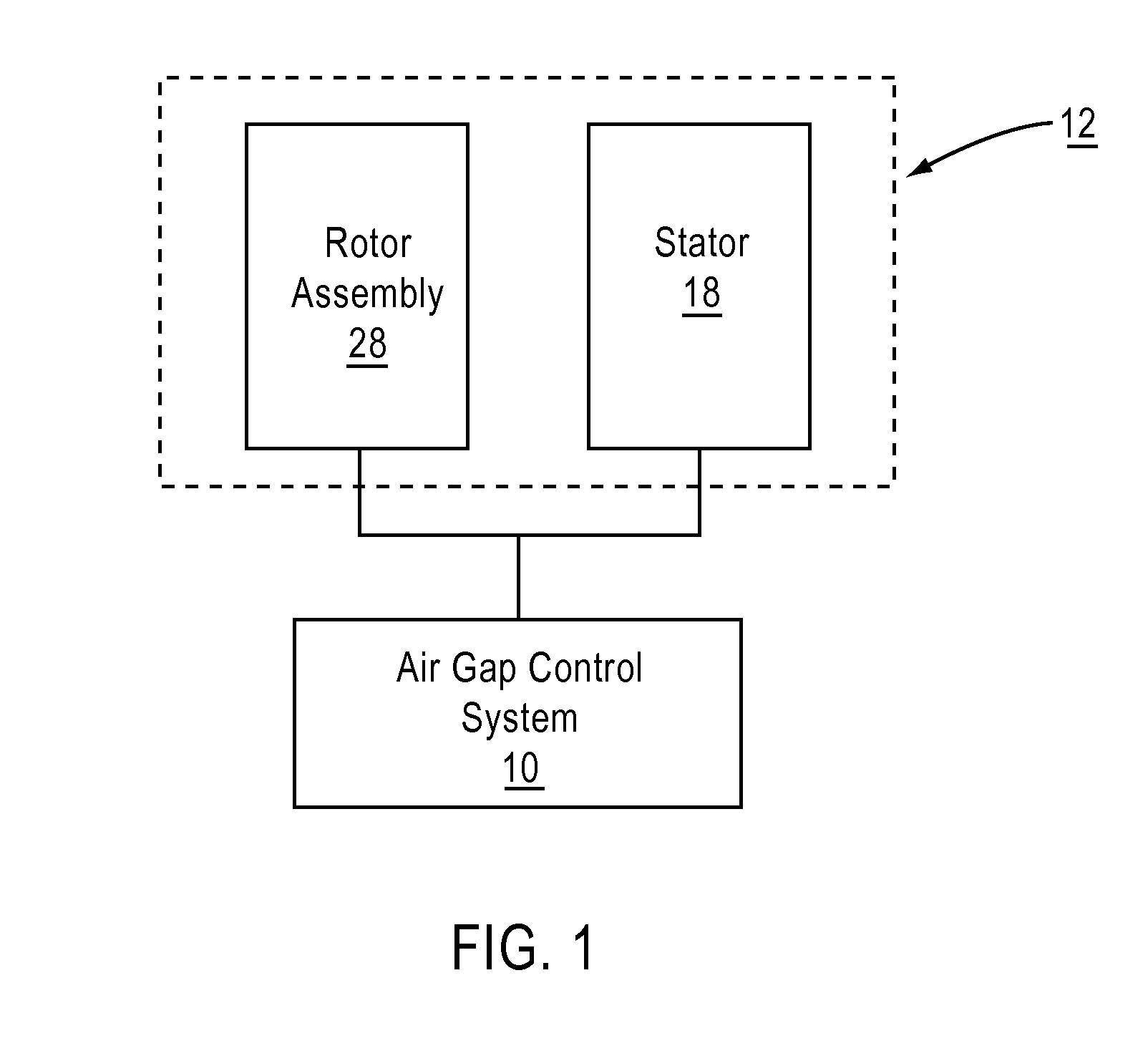
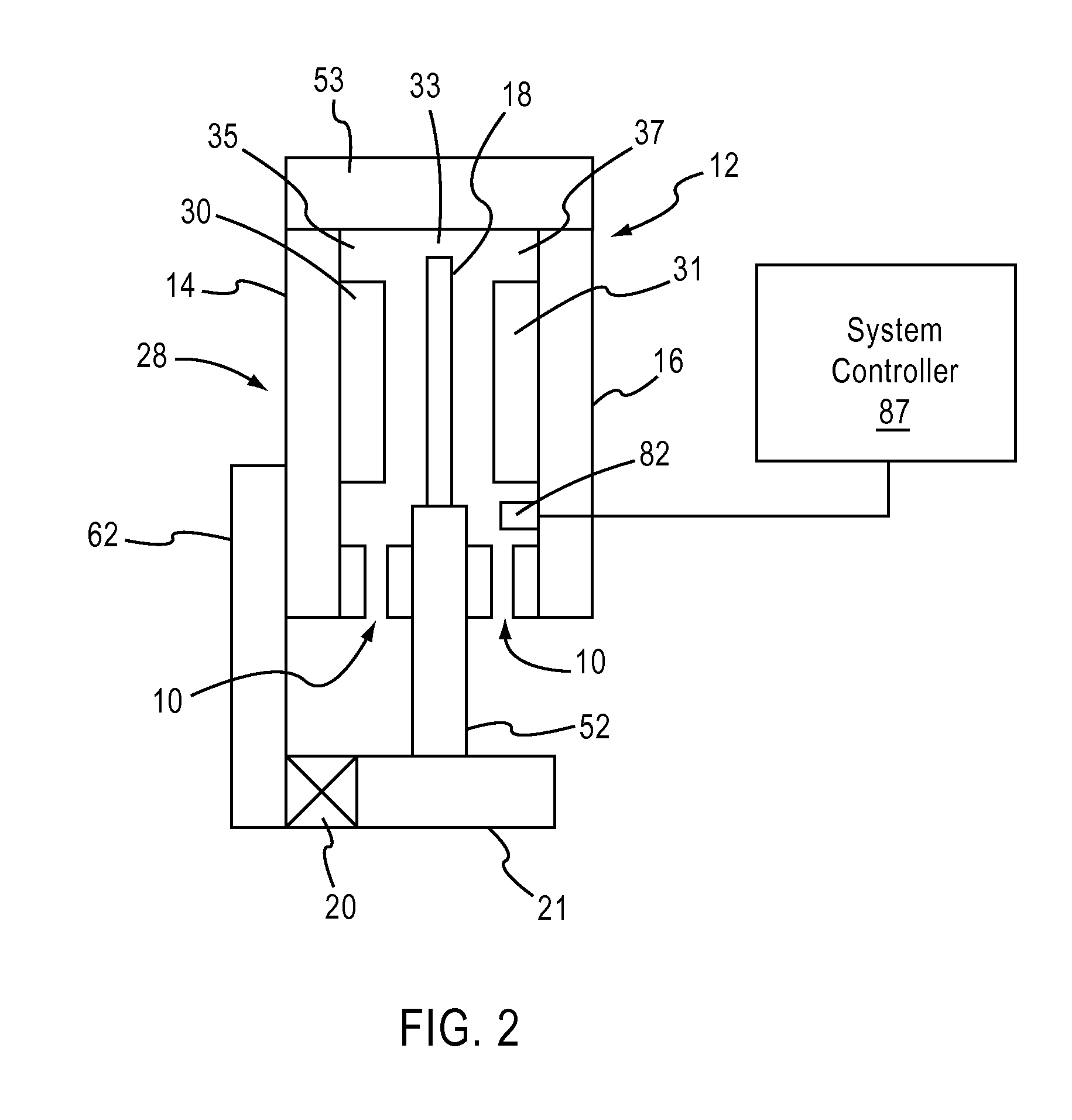
[0032]An air gap control system as described herein can be implemented in many applications where maintaining a constant gap is desired for machine performance and / or safe operation of the machine. In some embodiments, an air gap control system is described herein that can be used to maintain a clearance between the rotor assembly and stator by making one of the stator structure and the rotor structure relatively soft or compliant and the other of the stator structure and the rotor structure relatively stiff, and by transmitting a force from the stiff member to the compliant member to maintain a minimum gap clearance. When the stiff member is displaced or deflected, it transmits a force to the compliant member, causing the compliant member to deflect in a similar manner so as to maintain a constant or substantially constant gap size. The air gap control system can provide a locating stiffness between the rotor and stator, such that the air gap control stiffness becomes the dominant ...


PUM


Abstract

In one embodiment, an apparatus includes a first member that supports a magnetic flux carrying member and a second member that supports a magnetic flux generating member disposed for movement relative to the first member. An air gap control system is coupled to at least one of the first member or the second member and includes an air gap control device that is separate from a primary magnetic flux circuit formed between the first member and the second member. The air gap control device is configured to exert a force on one of the first and second members in response to movement of the other of the first and second members in a direction that reduces a distance between the first and second members to maintain a minimum distance between the first and second members and / or substantially center the one of the first and second members within the other.

Description

PRIORITY[0001]This application claims priority to and the benefit of U.S. Provisional Application Ser. No. 61 / 517,040, entitled “Air Gap Control System,” filed Apr. 12, 2011, the disclosure of which is incorporated herein by reference in its entirety.FIELD OF THE INVENTION[0002]Embodiments described herein relate to an air gap control system, and more particularly to an air gap control system for maintaining a minimum gap clearance in electromagnetic machines.BACKGROUND OF INVENTION[0003]Typical electromagnetic machines function by exposing electrically conductive windings in a stator to a magnetic field produced by magnets mounted on a turning rotor. The size of the air gap between the stator and the rotor is an important design variable, as the electromagnetic efficiency of such machines tends to improve as the air gap size is reduced. Maintaining a constant air gap size is also important, both to avoid a collision between the rotor and the stator and to avoid unwanted currents, f...

Claims


Application Information

Patent Timeline
Patent Type & Authority Applications(United States)
IPC IPC(8): H02P31/00H02K7/09
CPCH02K7/09H02K21/12H02K41/031H02P25/021H02K2213/09H02K21/026H02K2201/03H02P25/024H02K21/24H02K7/088H02K7/08
Inventor SMITH, JAMES S.JORE, MATTHEW B.KVAM, MICHAEL A.SAMSEL, DAVIDBUTTERFIELD, JR., CHARLES PERRYSULLIVAN, BRIAN J.
Owner BWP GRP
Why Eureka
Try Eureka