Low voltage isolation switch, in particular for a transmission channel for ultrasound applications

a low-voltage isolation switch and transmission channel technology, applied in electronic switching, transistors, electrical apparatus, etc., can solve the problems of high parasitic capacitance in parallel to the transducer, the ultrasound reflection is not complete, and the driving circuit of the ultrasonic transducer is rather large in size, so as to reduce the quality of the echo signal

Active Publication Date: 2012-10-18
STMICROELECTRONICS SRL
View PDF3 Cites 12 Cited by
  • Summary
  • Abstract
  • Description
  • Claims
  • Application Information

AI Technical Summary

Benefits of technology

[0018]The echo signal or return acoustic wave is converted into an electric wave that is a signal of some millivolts of width, signal that is then amplified by low noise amplifier circuits, connect

Problems solved by technology

It is to be noted that, the big impedance difference between a bone and a tissue being considered, with sonography it is not possible to see behind a bone, which causes a total reflection of the ultrasounds, while air or gas zones give “shade”, causing a partia

Method used


Image

  • Low voltage isolation switch, in particular for a transmission channel for ultrasound applications
  • Low voltage isolation switch, in particular for a transmission channel for ultrasound applications
  • Low voltage isolation switch, in particular for a transmission channel for ultrasound applications

Examples


Embodiment Construction

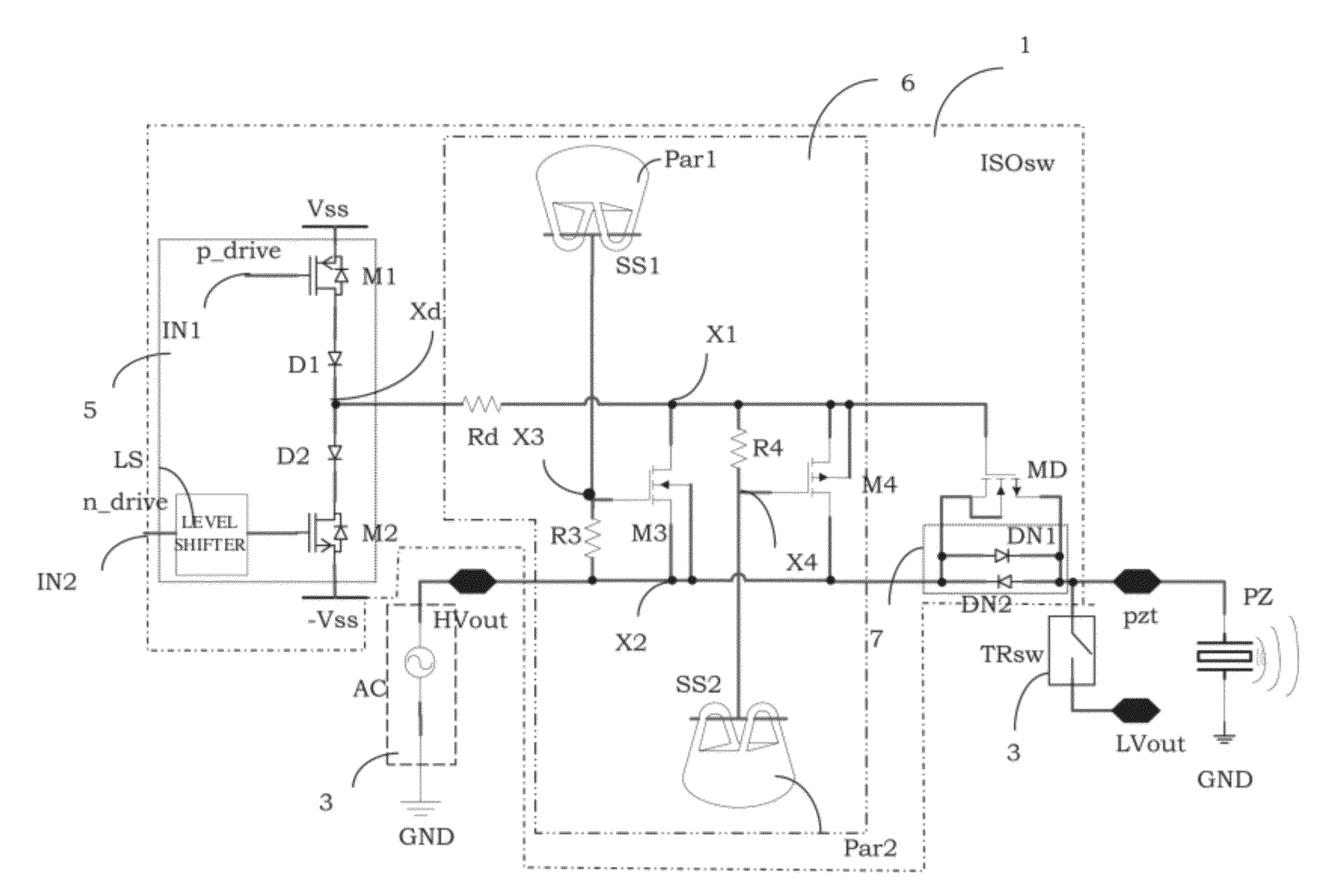
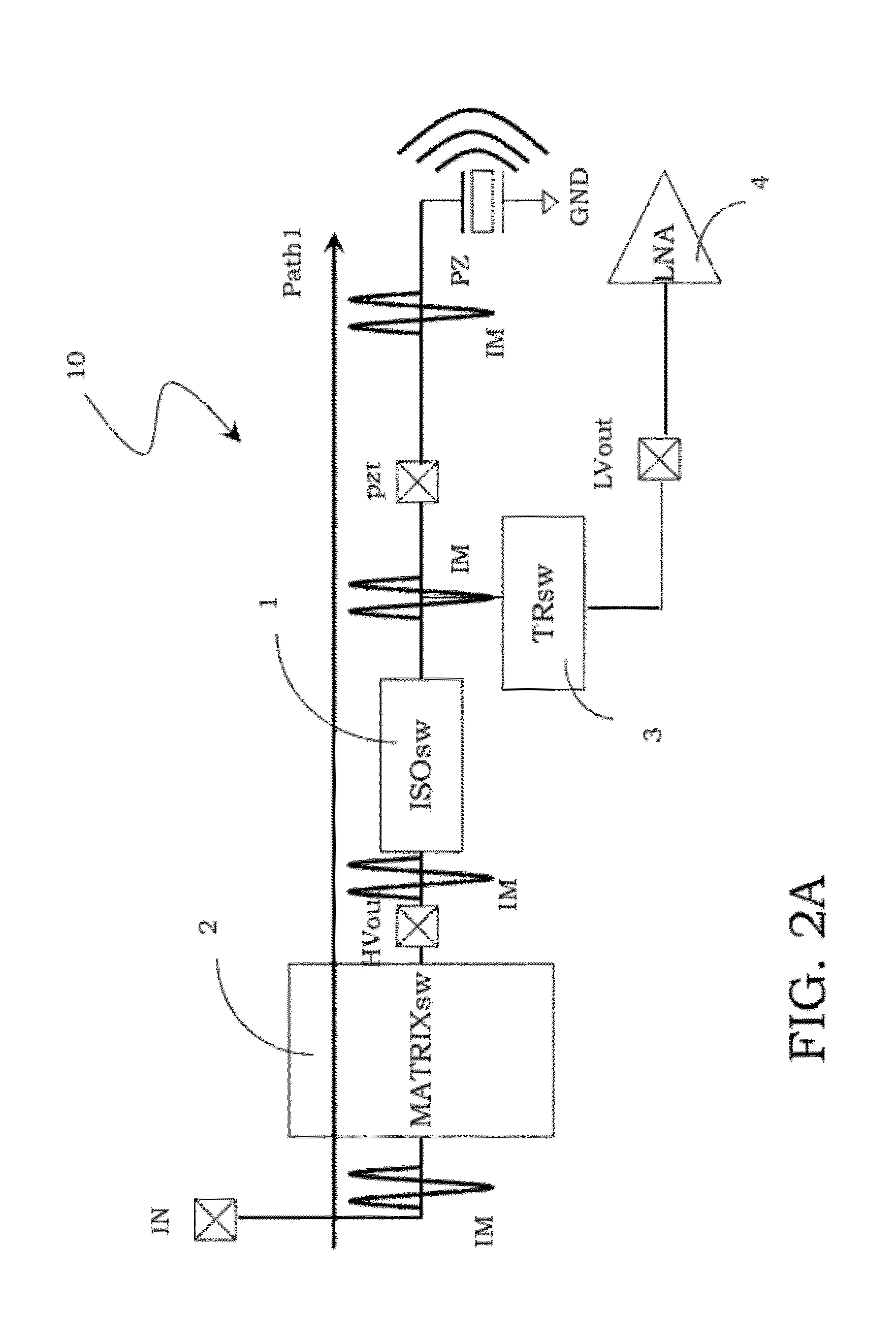
[0052]With reference to these figures, and in particular to FIGS. 2A, 2B and 2C, 10 globally and schematically indicates a transmission channel of an impulsive signal for an ultrasound transducer, in particular a piezoelectric transducer PZ.

[0053]By way of illustration, only an output section of the transmission channel 10 has been actually shown, which is connected to the piezoelectric transducer PZ and supplies it with an impulsive signal IM generated by suitable circuitry (not shown) and already present on an input terminal IN.

[0054]In particular, the transmission channel 10 firstly comprises a matrix (MATRIXsw) 2 of high voltage switches electrically coupled between the input terminal IN and a first high voltage output terminal HVout, whereon the input impulsive signal IM is transmitted.

[0055]Furthermore, the transmission channel 10 comprises a second low voltage output terminal LVout suitable for being connected to a transconductance cell 4 (LNA) and via a connection terminal p...


PUM


Abstract

A low voltage isolation switch is coupled between an input terminal suitable for receiving a high voltage signal and an output terminal suitable for transmitting this high voltage signal to a load. The isolation switch includes a first driving transistor coupled between a first reference terminal and an intermediate node, a second driving transistor coupled between the intermediate node and the second reference terminal, a control transistor connected across a diode block coupled between the input and output terminals. The control transistor has a control terminal connected to the intermediate node through a low voltage decoupling block that includes first and second substrate terminals, first and second parasitic capacitive element connected to these first and second substrate terminals, and first and second decoupling transistors coupled in parallel to each other and having control terminals connected to the first and second parasitic capacitive elements, respectively.

Description

BACKGROUND[0001]1. Technical Field[0002]The present disclosure relates to a low voltage switch. The disclosure also relates to a transmission channel of a high voltage signal to a load, in particular a piezoelectric transducer and to a corresponding driving method. The disclosure particularly, but not exclusively, relates to a low voltage switch for a transmission channel for ultrasound applications and the following description is made with reference to this field of application by way of illustration only.[0003]2. Description of the Related Art[0004]As it is well known, sonography or ultrasonography is a system of medical diagnostic testing that uses ultrasonic waves or ultrasounds and is based on the principle of the transmission of the ultrasounds and of the emission of echoes and is widely used in the internal medicine, surgical and radiological fields.[0005]The ultrasounds normally used are comprised between 2 and 20 MHz. The frequency is chosen by taking into consideration th...

Claims


Application Information

Patent Timeline
IPC IPC(8): H03K17/687
CPCB06B1/0215H03K17/06H03K17/74H03K17/6872H03K17/693H03K17/08122
Inventor BOTTAREL, VALERIARICOTTI, GIULIOQUAGLIA, FABIOGIOVANNONE, JURI
Owner STMICROELECTRONICS SRL
Why Eureka
Try Eureka