
Enhanced visualization for medical images

a technology of enhanced visualization and medical images, applied in image enhancement, image analysis, instruments, etc., can solve the problems of affecting the display of pneumothorax, difficult to detect pneumothorax in radiographic images, and complicating pneumothorax detection, so as to achieve pneumothorax enhancement in chest x-ray images

Inactive Publication Date: 2012-10-18
CARESTREAM HEALTH INC
View PDF10 Cites 25 Cited by
  • Summary
  • Abstract
  • Description
  • Claims
  • Application Information

AI Technical Summary

Benefits of technology

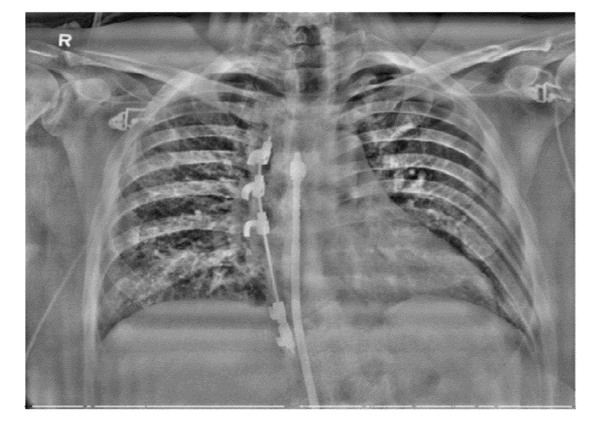
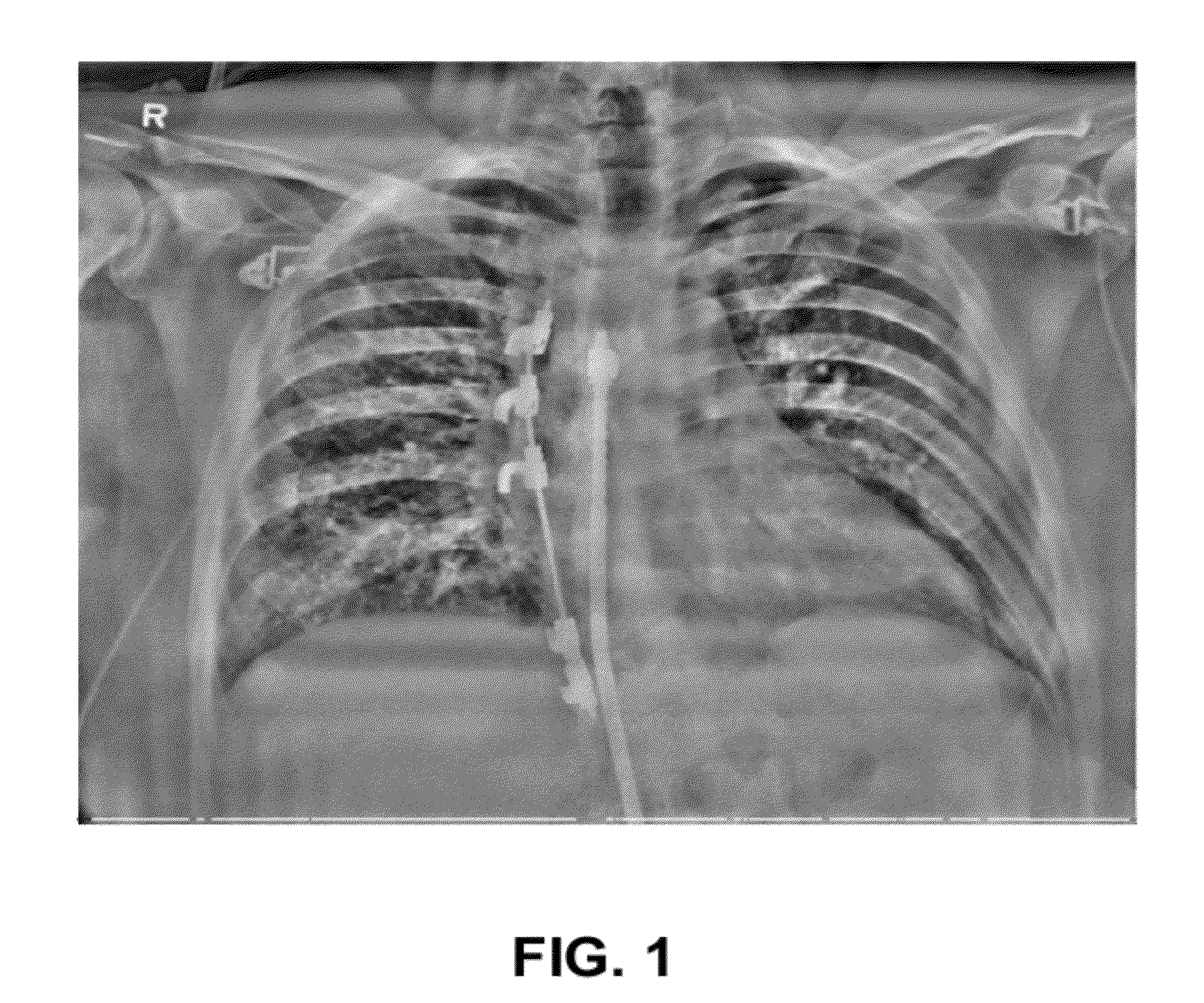
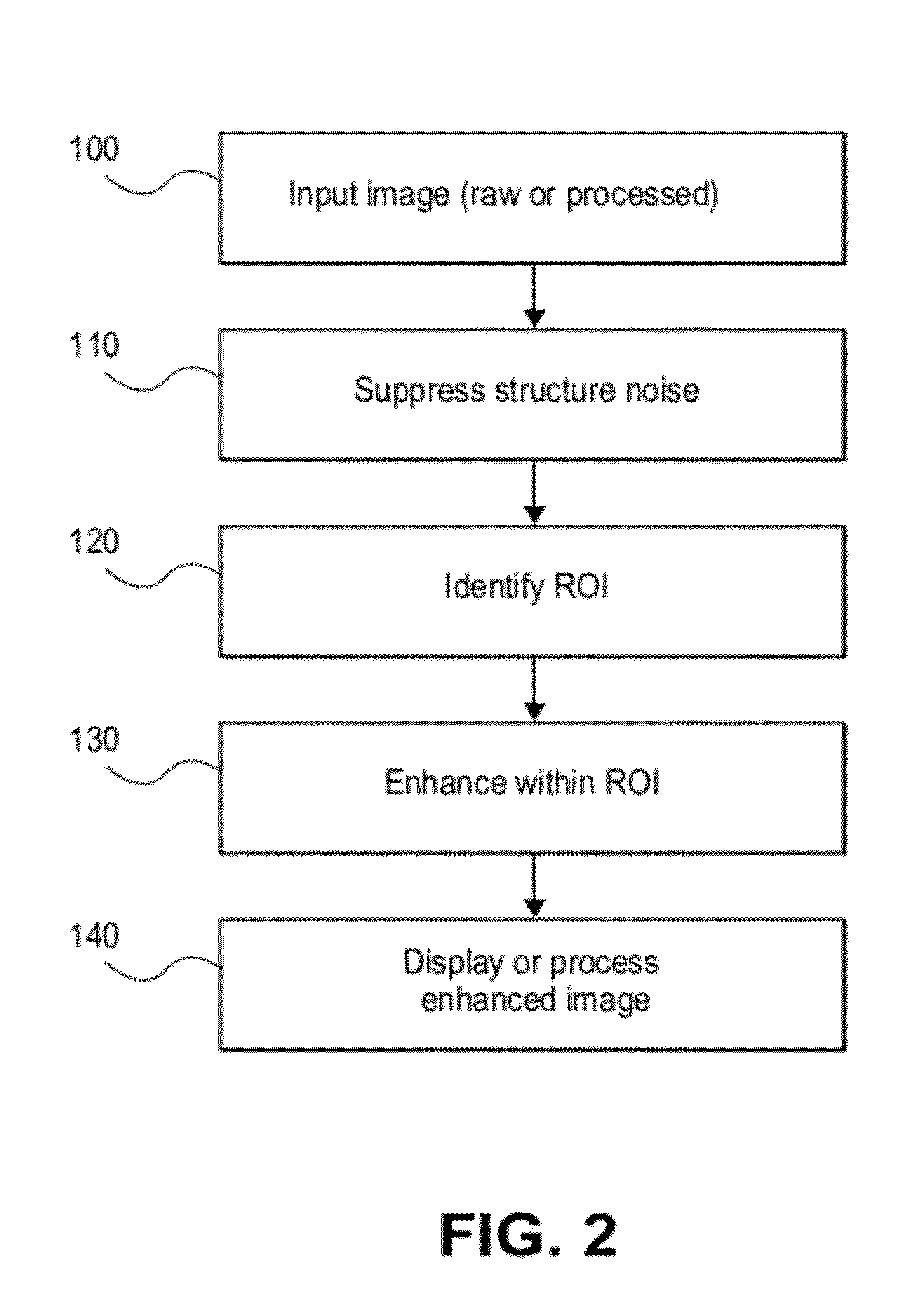
[0017]According to one aspect of the present invention, there is provided a method for enhancing a radiographic image, executed at least in part on a host processor and comprising: obtaining image data for the radiographic image; generating conditioned image data by increasing differences between neighboring portions of at least a relatively uniform area of the radiographic image; generating an enhanced image by applying contrast limited adaptive histogram equalization to the conditioned image data; applying interpolation to the enhanced image; and displaying the enhanced image.

Problems solved by technology

Although pneumothoraces are clinically important abnormalities, it is often difficult to detect them in the radiographic image.
Some of the problems that complicate pneumothorax detection are due to the location of this condition, since there can be some overlap between the pneumothorax region and nearby ribs and clavicle.
Edge detection and rib removal routines, which can be helpful for allowing improved visibility of some types of conditions, can be detrimental to display of pneumothorax in many cases, since such routines can often mistake the boundary along which pneumothorax is detected as a type of edge and, deriving this inaccurate information from the image, incorrectly apply edge suppression.
This may result in actually reducing the visibility of the pneumothorax condition.
Because of this, and as a result of similar problems, it can be particularly difficult to detect pneumothorax using a computer-aided detection (CAD) system.
However, due to the complexity of the image analysis problem and due to the relative subtlety of its visual indications, pneumothorax detection and enhancement continue to present a problem that is elusive for conventional image processing and analysis approaches.
Because of the diverse types of tissues and structures involved, the chest x-ray presents a number of challenges to conventional techniques for image enhancement.
One set of problems for improving the detectability of pneumothorax as well as for detecting lung nodules or line and tube placement relates to imaging differences between lung tissue and tissues in the abdominal region.
Because of this, image enhancement techniques that may work well over non-uniform regions of the image can tend to generate artifacts when applied over the more uniform region or when applied along the boundaries of the more uniform area.
While this works well with some types of images, however, histogram equalization is indiscriminate and can actually enhance the visibility of noise as well as the intended signal.
One artifact that often results from CLAHE pre-processing is ripple, a low-frequency imaging effect that is most visible over uniform areas of the image (such as the abdominal region), but also affects less uniform portions of the image.
Where ripple occurs, there can be difficulty in detecting the edges of structures, such as those that show a pneumothorax condition, for example.
However, this type of solution can compromise image quality and reduce contrast, losing information and effectively defeating the processing for contrast enhancement that produced ripple in the first place.
Other, more complex solutions for reducing ripple in the processed image include processes that adjust or modify the CLAHE processing scheme for individual tiles.
However, if proper care is not given in selecting the clipping level or other CLAHE related variables, the difference in local contrast enhancement using such processing from one tile to another tile may have negative effects on image uniformity in terms of detail contrast.
Achieving differences in detail contrast enhancement, such as blurring and losing contrast over areas with a lower detail contrast enhancement when compared to areas with higher contrast enhancement, can have negative effects.
While this processing may reduce ripple somewhat, its results often fall short of diagnostic quality if a consistent detail contrast in an image is required.

Method used


Image

  • Enhanced visualization for medical images
  • Enhanced visualization for medical images
  • Enhanced visualization for medical images

Examples


Embodiment Construction

[0035]The following is a detailed description of the preferred embodiments of the invention, reference being made to the drawings in which the same reference numerals identify the same elements of structure in each of the several figures.

[0036]The method of the present invention executes on a computer or other type of control logic processor, which may include a dedicated microprocessor or similar device. A computer program product used in an embodiment of the present invention may include one or more storage media, for example; magnetic storage media such as magnetic disk or magnetic tape; optical storage media such as optical disk, optical tape, or machine readable bar code; solid-state electronic storage devices such as random access memory (RAM), or read-only memory (ROM); or any other physical device or media employed to store a computer program having instructions for controlling one or more computers to practice the method according to the present invention.

[0037]It is noted ...


PUM


Abstract

A method for enhancing a radiographic image. The method includes obtaining image data for the radiographic image, generating conditioned image data by increasing differences between neighboring portions of at least a relatively uniform area of the radiographic image, generating an enhanced image by applying contrast limited adaptive histogram equalization to the conditioned image data, applying interpolation to the enhanced image, and displaying, storing, or transmitting the enhanced image.

Description

FIELD OF THE INVENTION[0001]The invention relates generally to the field of diagnostic imaging and more particularly to methods for enhanced visualization of chest x-ray images for improving detectability of conditions such as pneumothorax.BACKGROUND OF THE INVENTION[0002]The chest x-ray is a useful diagnostic tool that assists in detecting a number of patient conditions and for imaging a range of skeletal and organ structures. In clinical applications such as in the Intensive Care Unit (ICU), the chest x-ray can have particular value for indicating pneumothorax as well as for tube / line positioning, and other clinical conditions. Pneumothorax is a condition caused by an accumulation of air or gas in the pleural cavity, which can occur as a result of disease or injury. Radiographic detection of pneumothorax is commonly based on observing a subtle, fine curved-line pattern in the apical lung region, a dark pleural air space against the chest wall due to increased transparency, and a l...

Claims


Application Information

Patent Timeline
IPC IPC(8): G06K9/00
CPCG06T5/009G06T2207/30061G06T2207/10116G06T5/40G06T5/92
Inventor HUO, ZHIMINLAO, ZHIQIANGXU, FAN
Owner CARESTREAM HEALTH INC
Learn More