Compression method and air separation

a technology of air separation and compression method, which is applied in the direction of machines/engines, positive displacement liquid engines, light and heating apparatus, etc., can solve the problems of loss in efficiency and likely not operating along the peak efficiency operating line, and achieve the effect of less power, less power, and more energy efficiency

Inactive Publication Date: 2012-10-18
PRAXAIR TECH INC
View PDF4 Cites 28 Cited by
  • Summary
  • Abstract
  • Description
  • Claims
  • Application Information

AI Technical Summary

Benefits of technology

[0009]When a multistage compression system is operated in accordance with the present invention, as set forth above, the flow rate is reduced during the turn down operating conditions while allowing the gas to be delivered at the pressure that is obtained during the normal operating conditions. Thus, the method of the present invention allows the multistage compression system to be used in applications where a stable pressure is required under all operational regimes. In addition to the foregoing, the method of the present invention is particularly energy efficient when the multistage compression system is operated during turn down conditions. The reason for this is that the power consumed by a multistage compression system have multiple stages is greatest at the initial compression stage because the volumetric flow rate is greatest in such stage due to the fact that the gas has the lowest density while being compressed in the initial stage. As the gas is successively compressed, the density increases and consequently less power is consum...

Problems solved by technology

The successive stages will recover the reduction of the pressure in the first stage of compression due to turn down and as such, will very likely not operate along their peak efficiency operating line.
Howe...

Method used


Image

  • Compression method and air separation
  • Compression method and air separation
  • Compression method and air separation

Examples


Embodiment Construction

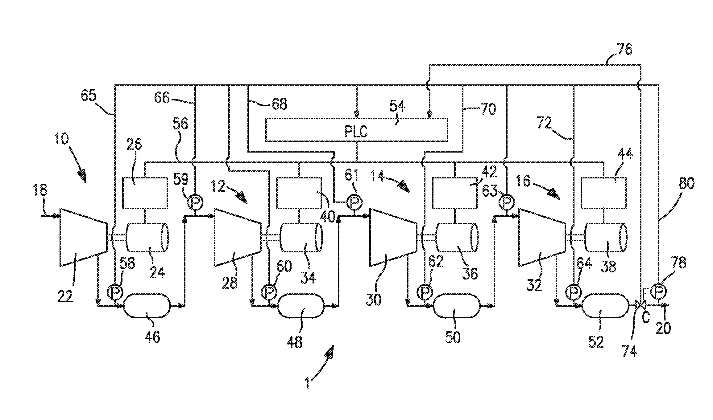
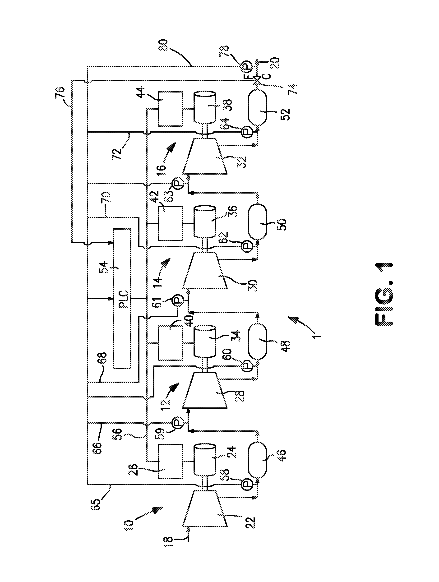
[0023]With reference to FIG. 1, a multistage compression system 1 in accordance with the present invention is illustrated. Multistage compression system 1 is a multistage compression unit having four compression stages 10, 12, 14 and 16 that is designed to compress a gas contained in a feed stream 18 from a lower pressure to a higher pressure and thereby produce a compressed gas stream 20 containing the gas at the higher pressure. It is understood that a multistage compression system in accordance with the present invention could include a greater or lesser number of stages.

[0024]Compression stage 10 is provided with a compressor 22 that is driven by a variable speed motor 24. It is understood that the compressor 22 can be centrifugal compressor of the type described above that is driven by a variable speed electric permanent magnet motor. In compression stage 10, the variable speed motor 24 is controlled by a speed controller 26 that could be a variable frequency controller where t...


PUM


Abstract

A compression method, a multistage compression system and an air separation method and plant in which a gas is compressed in a series of compression stages to produce a compressed gas and each of the compression stages incorporate a variable speed compressor. In such compression method and system, the compressed air is produced at a pressure that remains stable during both normal operational conditions and during turn down conditions during which the flow rate of the gas is reduced. This reduction is accomplished by reducing the speed of the compressor in an initial compression stage such that the compressor operates at a point along its peak efficiency operating line at which the pressure ratio is directly proportional to the flow rate and such that the lower turn down flow rate is obtained at a reduced pressure which is made up in successive compression stages.

Description

RELATED APPLICATIONS[0001]This application is a continuation-in-part of prior U.S. application Ser. No. 13 / 087,734, filed on Apr. 15, 2011, which is incorporated herein by reference.FIELD OF THE INVENTION[0002]The present invention relates to a method and system for compressing a gas and an air separation method and plant incorporating such method and system in which a gas or air is compressed in a series of compression stages to a higher pressure that is maintained both at normal operating conditions and during turndown operational conditions when a lower flow rate of the gas or air is required. More particularly, the present invention relates to such a method and system and air separation method and plant in which the compression stages have variable speed motors driving compressors and the speed of each of the compressors is adjusted during turndown such that an initial of the compression stages operates at a point along a peak efficiency operating line.BACKGROUND OF THE INVENTIO...

Claims


Application Information

Patent Timeline
IPC IPC(8): F04D27/00F04D25/16F04D25/02
CPCF04D17/12F04D25/0606F25J3/04296F25J3/04303F25J3/044F25J3/04412F04D27/0261F25J3/04781F25J3/04812F25J3/04018F25J3/0409F25J3/04121F25J3/04133F25J2230/40Y02B30/70
Inventor DEMORE, DANIEL D.BAKER, ROBERT L.ROYAL, JOHN H.
Owner PRAXAIR TECH INC
Why Eureka
Try Eureka