
Composite bipolar plate

a technology composite bipolar plates, which is applied in the field of composite bipolar plates for fuel cells, can solve the problems of relatively low average manufacturing cost of conventional bipolar plates, and achieve the effect of relatively low average manufacturing cost of composite bipolar plates

Inactive Publication Date: 2012-10-18
NAT CENT UNIV
View PDF2 Cites 0 Cited by
  • Summary
  • Abstract
  • Description
  • Claims
  • Application Information

AI Technical Summary

Benefits of technology

[0007]It is another object of the present invention to provide a composite bipolar plate, which buffers external pressure to protect against cracking and has an average manufacturing cost much cheaper than conventional graphite bipolar plates.
[0008]To achieve these and other objects of the present invention, a composite bipolar plate comprises a frame defining therein an inner edge and a first inlet and a first outlet at the inner edge, a bonding layer bonded to the inner edge of the frame, and a runner plate defining a plurality of flow channels and a second inlet and a second outlet respectively disposed in communication with the flow channels and being bonded to the bonding layer to become affixed to the frame and to have the second inlet be connected to the first inlet and the second outlet be connected to the first outlet for enabling a fuel to flow from the second inlet into the flow channels toward the outside of the runner plate via the second outlet.
[0009]Thus, in one same dimension, the composite bipolar plate is much lighter than a conventional metal bipolar plate. Further, because the graphite runner plate is bonded to the flexible frame, the flexible frame buffers external pressure, protecting the graphite runner plate against cracking. Further, because the frame is suitable for mass production by means of injection molding, the average manufacturing cost of the composite bipolar plate is relatively lower than the conventional bipolar plates.

Problems solved by technology

Further, because the frame is suitable for mass production by means of injection molding, the average manufacturing cost of the composite bipolar plate is relatively lower than the conventional bipolar plates.

Method used


Image

  • Composite bipolar plate
  • Composite bipolar plate
  • Composite bipolar plate

Examples


Embodiment Construction

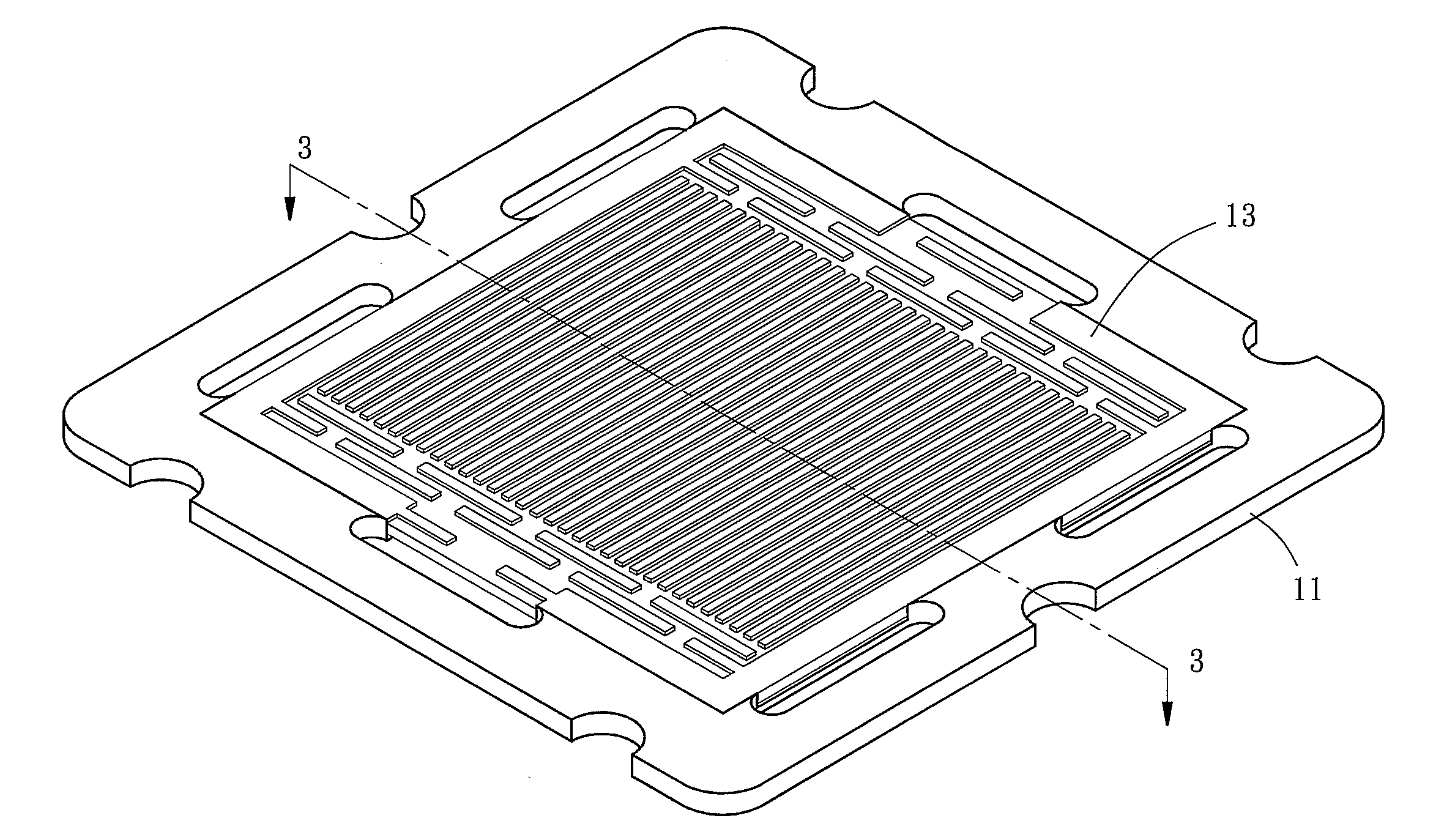
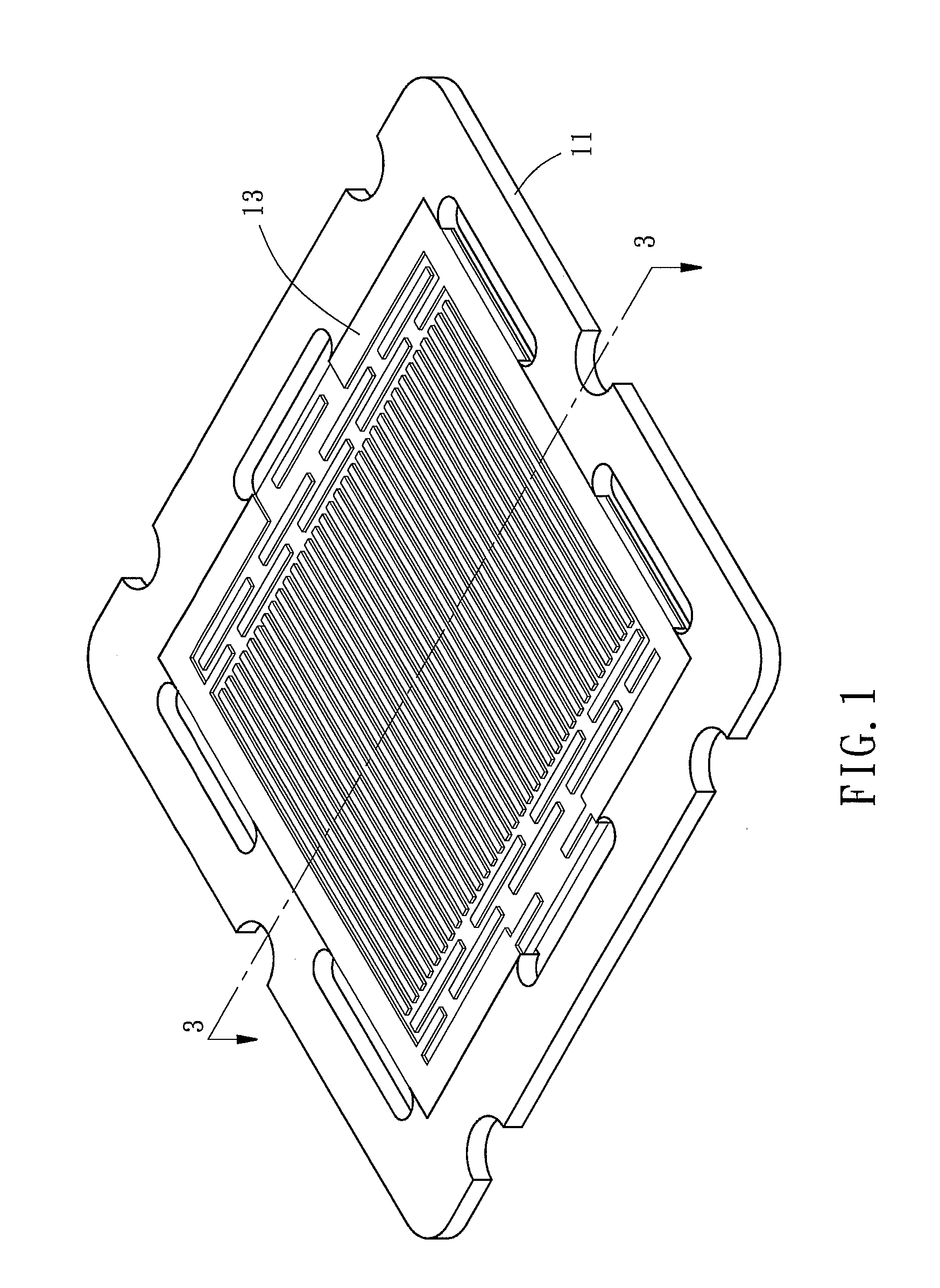
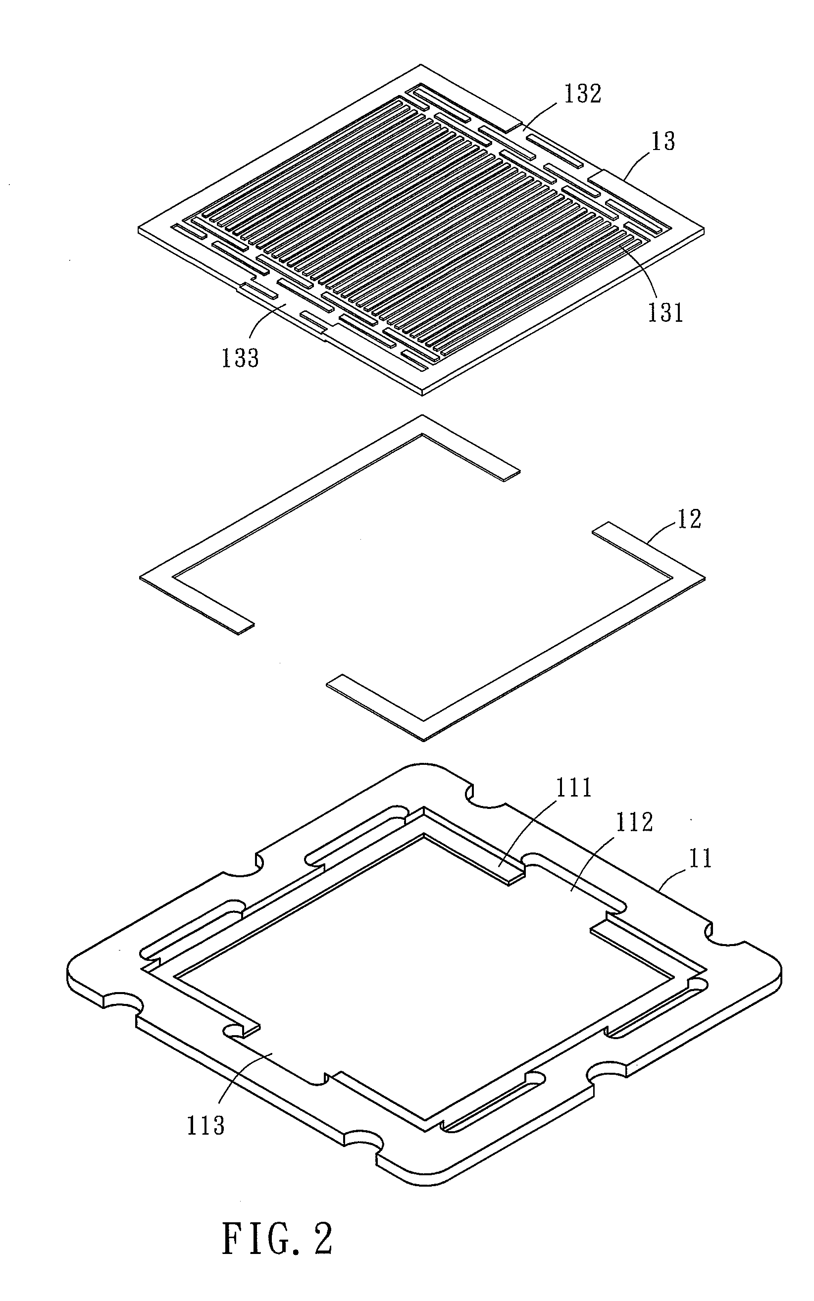
[0015]Referring to FIGS. 1-3, a composite bipolar plate in accordance with the present invention is shown comprising a frame 11, a bonding layer 12 and a runner plate 13.

[0016]The frame 11 comprises an inner edge 111, a first inlet 112 and a first outlet 113 defined at the inner edge 111. It is to be noted that, in this embodiment, the thickness of the frame 11 can range from 0.75 mm to 10, preferably within 0.75 mm˜3 mm. Further, the frame 11 is selected from the material group of polyester, polyamide, polystyrene, polyolefin consisting of polyethylene and polypropylene, and their copolymers.

[0017]The bonding layer 12 is bonded to the inner edge 111 of the frame 11. Further, the bonding layer 12 is selected from the group of silicone resin, epoxy resin, acrylic resin and bicomponent resins polymerized from polyester and urethane.

[0018]The runner plate 13 defines a plurality of flow channels 131 and a second inlet 132 and a second outlet 133 in communication with the flow channels 1...


PUM

PropertyMeasurementUnit
thicknessaaaaaaaaaa
thickaaaaaaaaaa
proton permeableaaaaaaaaaa

Abstract

A composite bipolar plate includes a frame defining therein an inner edge and a first inlet and a first outlet at the inner edge, a bonding layer bonded to the inner edge of the frame, and a runner plate defining a plurality of flow channels and a second inlet and a second outlet respectively disposed in communication with the flow channels and being bonded to the bonding layer to become affixed to the frame and to have the second inlet be connected to the first inlet and the second outlet be connected to the first outlet for enabling a fuel to flow from the second inlet into the flow channels toward the outside of the runner plate via the second outlet.

Description

BACKGROUND OF THE INVENTION[0001]1. Field of the Invention[0002]The present invention relates to fuel cells and more particularly, to a composite bipolar plate for fuel cells.[0003]2. Description of the Related Art[0004]Many different fuel cell batteries are known. Among the conventional fuel cells, proton exchange membrane fuel cells (PEMFC) is an optimal one practical for use in 3C home appliances or for home application. In a proton exchange membrane fuel cell, a membrane electrode assembly is provided comprising a proton permeable membrane bonded on one side to an anode and bonded on the opposite side to a cathode. In the aforesaid proton exchange membrane fuel cell architecture, the bipolar plate acts an important role. It isolates the reaction gas, conducts electric current, supports the electrodes, and provides heat dissipation and water drainage functions. Therefore, a bipolar plate is a key component in a proton exchange membrane fuel cell.[0005]At the present time, commerc...

Claims


Application Information

Patent Timeline
Patent Type & Authority Applications(United States)
IPC IPC(8): H01M8/04
CPCY02E60/50H01M8/0213H01M2008/1095H01M8/0228H01M8/0258H01M8/0221H01M8/0273H01M8/2483
Inventor TSENG, CHUNG-JENCHEN, FENG-CHANG
Owner NAT CENT UNIV
Learn More