
High power laser photo-conversion assemblies, apparatuses and methods of use

Active Publication Date: 2012-10-25
FORO ENERGY
View PDF33 Cites 107 Cited by
  • Summary
  • Abstract
  • Description
  • Claims
  • Application Information

AI Technical Summary

Benefits of technology

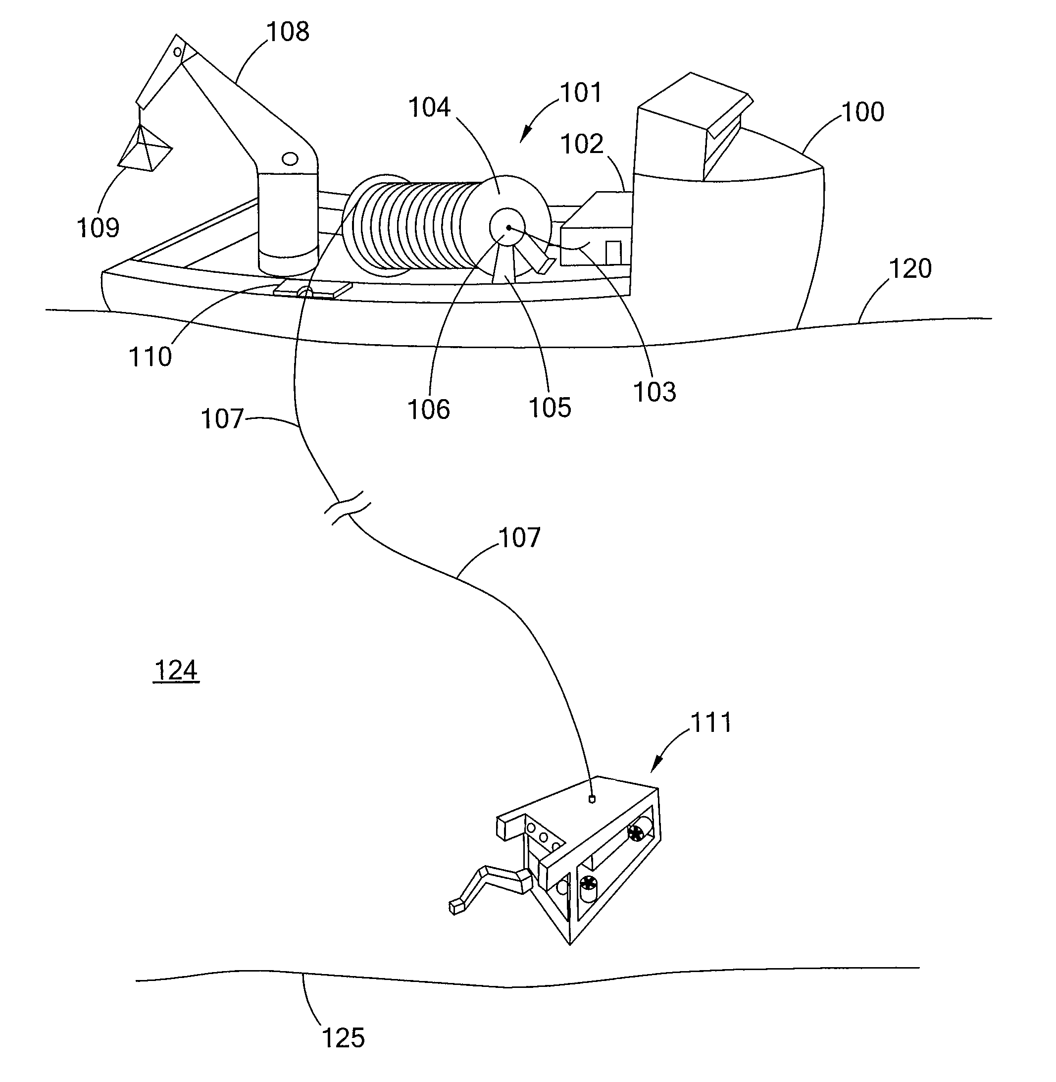
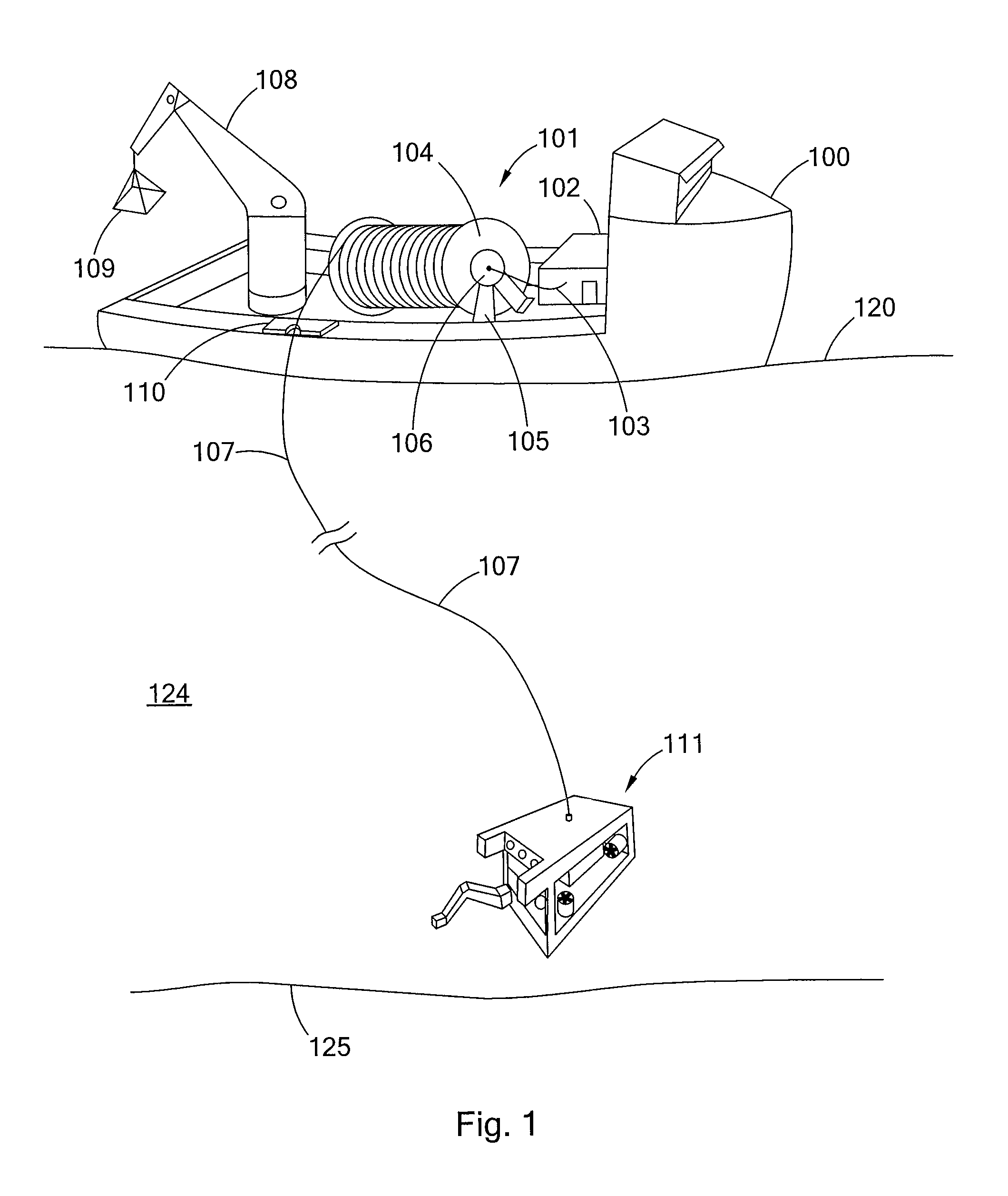
[0050]There is provided a method of performing laser powered operations by a subsea device, the method including: optically associating a subsea device with a high power laser by means of a high power laser tether having a high power laser fiber; lowering the subsea device into a body of water; propagating a high power laser beam; launching the high power laser beam into the high power laser fiber in the high power laser tether; transmitting the high power laser beam through the high power laser fiber to the subsea device without substantial loss of power; converting at least a portion of the laser beam into electrical energy; and, utilizing the electrical energy to power an operation of the subsea device. Such method may also be such that at least a portion of the laser beam is directed at a work area located below a surface of the body of water.

Problems solved by technology

In future years is it anticipated that such endeavors will increase and that new and more complicated underwater activities and structures will arise.
Regardless of the depth, performing subsea operations can be very difficult, costly, time-consuming and damagers.
These obstacles and risks, however, greatly increase, and one could say exponentially increase, as the depth of the water becomes greater, and in particular for deep (e.g., about 1,000 ft), very-deep (e.g., about 5,000 ft) and ultra-deep (e.g., about 10,000 ft and greater) depths.
As the complexity and power demands of subsea vehicles increases, so has the complexity and size of tethers, e.g., diameter, complexity, power capabilities, data capabilities, number of cables, wires, and components.
A significant and long-standing problem with subsea vehicles, and in particular floating subsea vehicles, such as ROVs, is the drag that the tether creates.
As tether length increases tether drag increases.
Similarly, as tether diameter increases tether drag increases.
Thus, a paradigm exists where deep operations require more power and the diameter of the tether is increased to handle the additional power, which in turn further increases the tether drag and requires yet more power.
Prior to the recent breakthroughs at Foro Energy, Inc., it was believed that the transmission of high power laser energy over great distances without substantial loss of power was unobtainable.
Moreover, in the design and operation of subsea vehicles and subsea equipment, as well as potentially other tethered equipment, the vicious design spiral presented by the tether-drag paradigm has been a long-standing problem.

Method used


Image

  • High power laser photo-conversion assemblies, apparatuses and methods of use
  • High power laser photo-conversion assemblies, apparatuses and methods of use
  • High power laser photo-conversion assemblies, apparatuses and methods of use

Examples


example 1

[0144]Turning to FIG. 20 there is shown an embodiment of a laser PV assembly having 1 single junction PV cell 2000 for use with a laser beam having a spectrum of the type shown in FIGS. 16-19. The single junction PV cell 2000 has a grid design 2002 optimized for low resistance, including 4 busbars 2003a, 2003b, 2003c, 2003d. The single junction PV cell 2000 has an antireflective coating 2004. The PV cell 2000 has a window 2010, a highly doped, low resistance emitter 2011, a base with band gap tailored to the laser energy 2012, a back surface field 2013, buffer layer(s) and / or substrate 2014 and a back contact 2005.

example 2

[0145]Turning to FIG. 21 there is shown an embodiment of a laser PV assembly having 1 triple junction PV cell 2100 for use with a laser beam having a spectrum of the type shown in FIGS. 16-19. The triple junction PV cell 2100 has a grid design 2102 optimized for low resistance, including 4 busbars 2103a, 2103b, 2103c, 2103d. The triple junction PV cell 2100 has an anti-reflection coating 2104. The PV cell has a top junction 2110, a middle junction 2112 and a bottom junction 2114. The junctions are connected together in series by tunnel junctions 2111 and 2113. Each of the top 2110, middle 2112 and bottom 2114 junctions has an emitter, base, back surface field, and may also include a window and buffer layer(s). The base of each junction is the same material, with a band gap tailored to the laser energy. The thickness of the base in each junction is chosen such that the current produced by each junction is approximately the same. Thus, the base is thinnest in the top junction 2110 and...

example 3

[0146]Turning to FIG. 22 there is shown an embodiment of a laser PV assembly 2200 having 4 PV cells 2201, 2202, 2203, 2204 connected in series for use with a laser beam having a spectrum of the type shown in FIGS. 16-19. The 4 PV cells 2201, 2202, 2203, 2204 may all have the same design, which may be similar to those shown in Examples 1 and 2. The cells are connected in series by wire bonds 2205 or other interconnections so that the total current out of the PV assembly 2200 is the lowest of the currents produced by the 4 PV cells 2201, 2202, 2203, 2204, and the voltage out of the assembly is approximately the sum of the voltages of the 4 PV cells 2201, 2202, 2203, 2204 when operating at that single current. In this illustration, power is extracted from the assembly by leads 2206.


PUM


Abstract

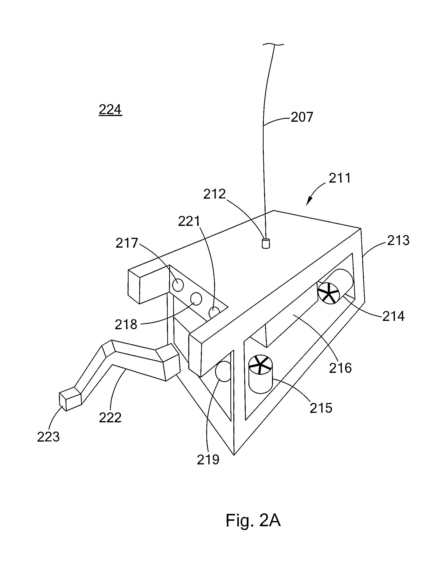
There is provided a high power laser system for powering a remotely located laser device, such as an ROV, using a high power laser fiber optic tether and a photo-conversion device, such as a laser photovoltaic assembly. Laser device systems, such as ROV systems that utilizes a high power laser cutting and / or cleaning tools are also provided.

Description

[0001]This application: (i) claims, under 35 U.S.C. §119(e)(1), the benefit of the filing date of Jan. 11, 2011 of provisional application Ser. No. 61 / 431,827; (ii) claims, under 35 U.S.C. §119(e)(1), the benefit of the filing date of Feb. 7, 2011 of provisional application Ser. No. 61 / 431,830; (iii) is a continuation-in-part of U.S. patent application Ser. No. 12 / 706,576 filed Feb. 16, 2010, which is a continuation-in-part of U.S. patent application Ser. No. 12 / 544,136 filed Aug. 19, 2009, and which claims under 35 U.S.C. §119(e)(1) the benefit of the filing date of Feb. 17, 2009 of provisional application Ser. No. 61 / 153,271, and the benefit of the filing date of Jan. 15, 2010 of provisional application Ser. No. 61 / 295,562; (iv) is a continuation-in-part of U.S. patent application Ser. No. 12 / 840,978 filed Jul. 21, 2010; (v) is a continuation-in-part of Ser. No. 12 / 543,968 filed Aug. 19, 2009; (vi) is a continuation-in-part of Ser. No. 12 / 544,136 filed Aug. 19, 2008, which claims ...

Claims


Application Information

Patent Timeline
IPC IPC(8): B63G8/08G01J1/04H01J40/14B63G8/00
CPCG02B6/4296B63G8/001B08B9/027B08B7/0071B08B9/023E21B41/04B08B7/0042B63G2008/007
Inventor ZEDIKER, MARK S.JONES-ALBERTUS, REBECCAFAIRCLOTH, BRIAN O.RINZLER, CHARLES C.MOXLEY, JOEL F.
Owner FORO ENERGY
Learn More