
Mass Spectrometer

a mass spectrometer and mass spectrometer technology, applied in mass spectrometers, particle separator tubes, isotope separation, etc., can solve the problem of relatively low mass resolution of the approach, and achieve the effect of improving mass resolution

Active Publication Date: 2012-10-25
MICROMASS UK LTD
View PDF5 Cites 14 Cited by
  • Summary
  • Abstract
  • Description
  • Claims
  • Application Information

AI Technical Summary

Benefits of technology

This approach significantly improves mass resolution by allowing for mass selective axial ejection, increasing the amplitude of oscillations at specific frequencies, and enabling more precise ion ejection and detection, compared to conventional resonance excitation methods.

Problems solved by technology

However, this approach has been found to suffer from a relatively low mass resolution given a fixed rate of scanning of the excitation frequency or the depth of the electrostatic potential well.

Method used


Image

  • Mass Spectrometer
  • Mass Spectrometer
  • Mass Spectrometer

Examples


Embodiment Construction

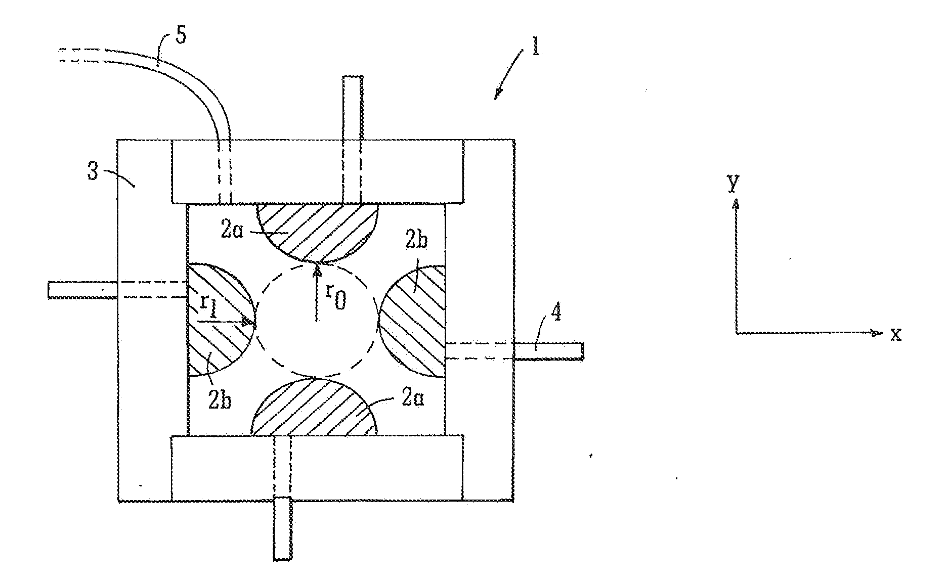
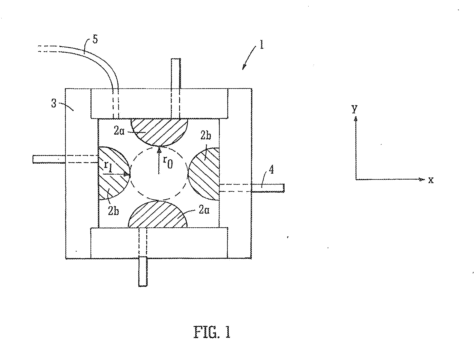
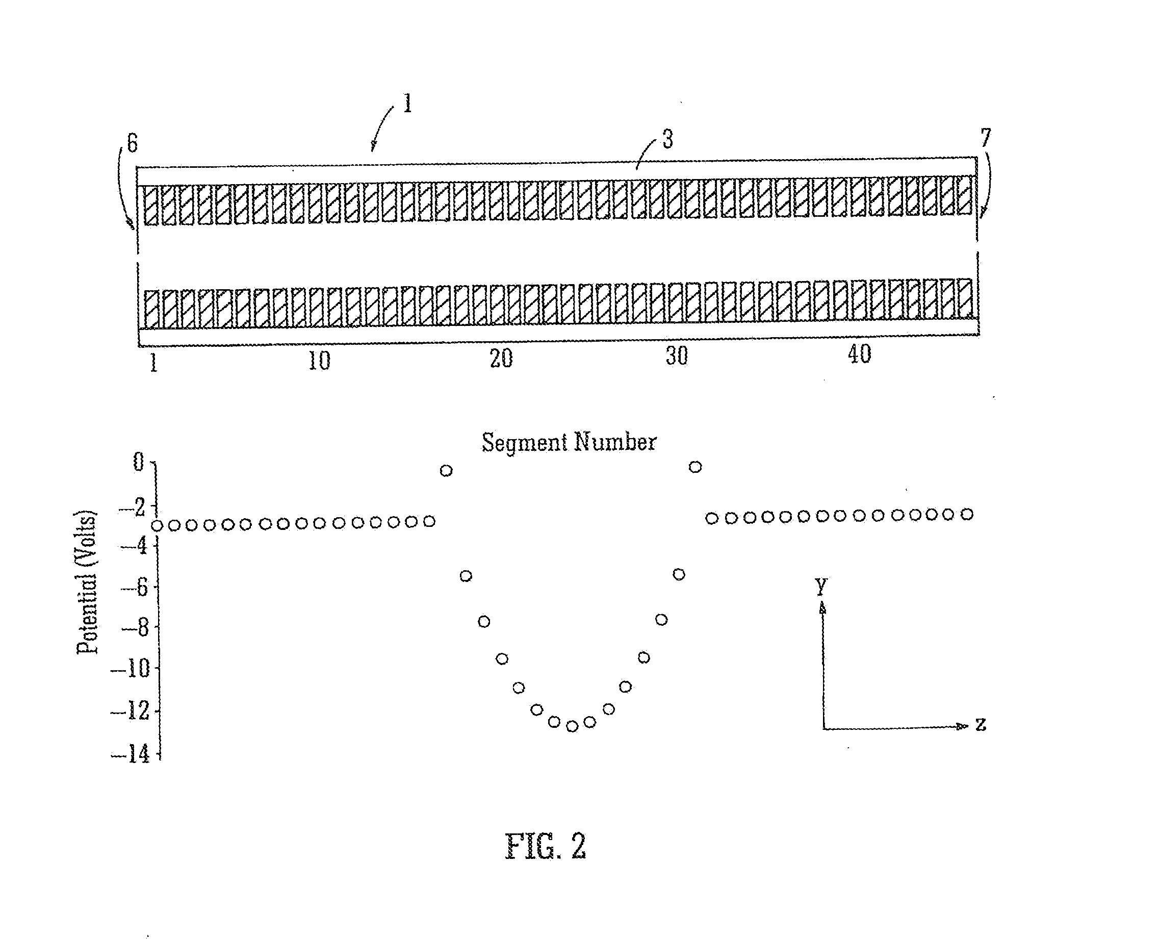
[0167]A preferred embodiment of the present invention will now be described with reference to FIG. 1. According to the preferred embodiment of the present invention a quadrupole rod set ion guide 1 is provided comprising electrodes 2a,2b having arcuate or hyperbolic surfaces. The electrodes 2a,2b are preferably split or axially divided into a plurality of axial segments. The number of axial segments is preferably arranged such that when electrostatic potentials are applied to each of the axial segments an electrostatic potential profile can be obtained which relaxes as close as possible to a quadratic function.

[0168]FIG. 1 shows two electrode pairs 2a,2b viewed along the z (axial) direction. The electrodes 2a,2b have a semi-circular cross-section and are mounted on a non-conductive or insulating substrate or block 3. The electrically insulating substrate or block 3 serves to ensure that the axial segments are positioned correctly with respect to each other and with respect to the ot...


PUM


Abstract

An ion trap mass analyser is disclosed comprising a segmented rod set. Ions are trapped radially within the mass analyser by a radial pseudo-potential well. The ions are also confined axially within a quadratic axial potential well. An AC voltage or potential is applied to the electrodes comprising the ion trap mass analyser in order to excite parametrically ions within the ion trap.

Description

CROSS REFERENCE TO RELATED APPLICATIONS[0001]This application is a continuation of the U.S. patent application Ser. No. 12 / 094,318 filed Sep. 25, 2008, which is the National Stage of International Application No. PCT / GB2006 / 004385 filed Nov. 23, 2006 which claims priority to and benefit of U.S. Provisional Patent Application Ser. No. 60 / 749,917, filed on Dec. 13, 2005 and priority to and benefit of United Kingdom Patent Application No. 0524042.9, filed Nov. 25, 2005. The entire contents of these applications are incorporated herein by reference.BACKGROUND OF THE INVENTION[0002]The present invention relates to a mass spectrometer and a method of mass spectrometry.[0003]U.S. Pat. No. 5,783,824 discloses a linear ion trap wherein an axial quadratic electrostatic potential is superimposed along the length of the ion trap. Ions are ejected axially from the in trap by resonance excitation wherein a supplementary excitation axial potential is applied to electrodes of the ion trap. The supp...

Claims


Application Information

Patent Timeline
Patent Type & Authority Applications(United States)
IPC IPC(8): H01J49/34H01J49/36H01J49/28
CPCH01J49/427H01J49/4235
Inventor GREEN, MARTIN
Owner MICROMASS UK LTD
Learn More