
Transmission channel for ultrasound applications

a technology for ultrasound and transmission channels, applied in the field of transmission channels, to achieve the effect of reducing the memory effect of this buffer block and facilitating the provision of desirable and predictable switching initial conditions

Active Publication Date: 2012-10-25
STMICROELECTRONICS SRL
View PDF10 Cites 16 Cited by
  • Summary
  • Abstract
  • Description
  • Claims
  • Application Information

AI Technical Summary

Benefits of technology

[0048]By changing the initial status also the output wave form is modified with the consequence that, the input control being identical, it is possible to obtain different outputs. In other words, the wave form of the output signal is function of the input signals and of the initial condition resulting from the switches previously occurred thus creating a sort of “memory effect”.
[0049]An embodiment facilitates providing desirable and predictable switching initial conditions in a transmission channel clamping circuit.
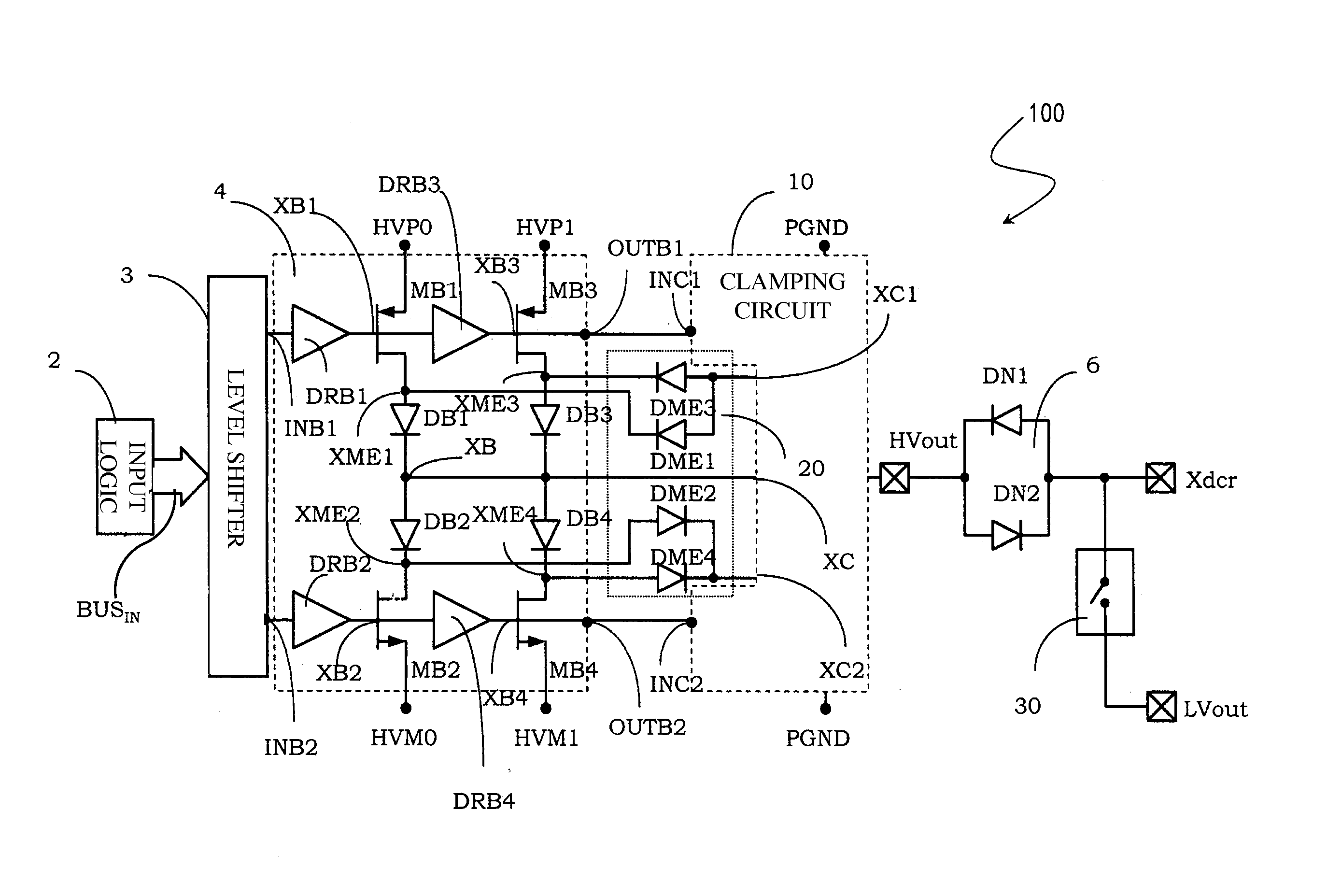
[0050]In an embodiment, high voltage diodes are connected to the inner nodes of the high voltage buffer block of the transmission channel to bias its condition between a pulse cycle and another one so as to reduce the memory effect of this buffer block, as well as of associating the clamp transistors to corresponding high voltage MOS transistors able to close themselves when the clamping circuit is active and likewise able to sustain positive and negative high voltages when instead the clamping circuit is not active and the transistors are in open configuration and of realising a switching circuit of the type comprising switching transistors and provided with bootstrap circuitry configured to drive the control terminals of these switching transistors with a following of a signal at the input of the switching circuit itself towards its output.

Problems solved by technology

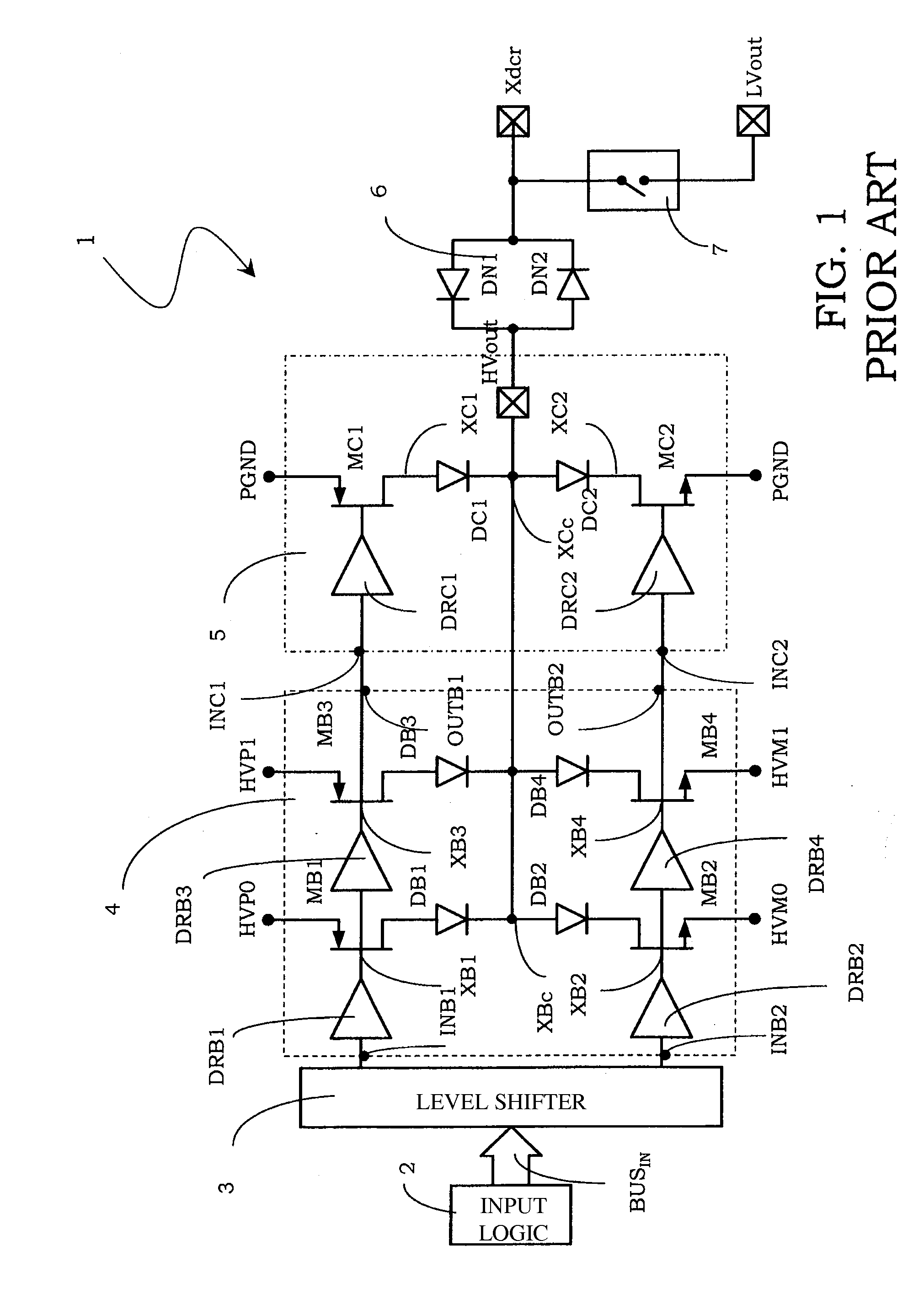
In case of connection of a load of great value, a high current can circulate through the high voltage clamp diodes DC1 and DC2, charging the junction intrinsic capacitances of the same diodes and causing a malfunction.

Method used


Image

  • Transmission channel for ultrasound applications
  • Transmission channel for ultrasound applications
  • Transmission channel for ultrasound applications

Examples


Embodiment Construction

[0105]In the following description, numerous specific details are given to provide a thorough understanding of embodiments. The embodiments can be practiced without one or more of the specific details, or with other methods, components, materials, etc. In other instances, well-known structures, materials, or operations, such as, for example, high-voltage transistors, diodes, drivers, etc., are not shown or described in detail to avoid obscuring aspects of the embodiments.

[0106]Reference throughout this specification to “one embodiment” or “an embodiment” means that a particular feature, structure, or characteristic described in connection with the embodiment is included in at least one embodiment. Thus, the appearances of the phrases “in one embodiment”“according to an embodiment” or “in an embodiment” and similar phrases in various places throughout this specification are not necessarily all referring to the same embodiment. Furthermore, the particular features, structures, or char...


PUM


Abstract

A transmission channel configured to transmit high-voltage pulses and to receive echoes of the high-voltage pulses includes a high voltage buffer, a voltage clamp and a switch. The voltage clamp may include clamping transistors and switching off transistors coupled together in series with body diodes in anti-series. The transmission channel may include a reset circuit configured to bias the transmission channel between pulses. The switch may include a bootstrap circuit.

Description

BACKGROUND[0001]1. Technical Field[0002]The present disclosure relates to transmission channels.[0003]The disclosure relates, but not exclusively, to transmission channels for ultrasound applications and the following description is made with reference to this field of application by way of illustration only.[0004]2. Description of the Related Art[0005]Sonography or ultrasonography is a system of medical diagnostic testing that uses ultrasonic waves or ultrasounds and is based on the principle of the transmission of the ultrasounds and of the emission of echo and is widely used in the internistic, surgical and radiological field.[0006]The ultrasounds normally used are, for example, between 2 and 20 MHz in frequency. The frequency is chosen by taking into consideration that higher frequencies have a greater image resolving power, but penetrate less in depth in the subject under examination.[0007]These ultrasounds are being normally generated by a piezoceramic crystal inserted in a pr...

Claims


Application Information

Patent Timeline
Patent Type & Authority Applications(United States)
IPC IPC(8): H03K17/567
CPCH03K19/018521G05F3/02H03K19/09443
Inventor ROSSI, SANDRORICOTTI, GIULIOGHISU, DAVIDE UGORICCIARDO, ANTONIO
Owner STMICROELECTRONICS SRL
Learn More