Cleaning method of plasma processing apparatus and plasma processing method

a plasma processing apparatus and plasma technology, applied in the direction of cleaning processes and apparatus, chemistry apparatus and processes, electric discharge tubes, etc., can solve the problems of difficult radical action on the processing target substrate, process may not be performed efficiently, and the electrolytic structure of the electrodes would be largely damaged by the hydrogen plasma

Inactive Publication Date: 2012-10-25
TOKYO ELECTRON LTD
View PDF5 Cites 18 Cited by
  • Summary
  • Abstract
  • Description
  • Claims
  • Application Information

AI Technical Summary

Benefits of technology

[0014]In accordance with the illustrative embodiment, it is possible to provide the plasma processing method and the cleaning method of the plasma processing appara

Problems solved by technology

When using the plasma of the hydrogen gas, if a capacitively coupled plasma processing apparatus of, e.g., a parallel plate type is used, an electrode therein would be largely damaged

Method used


Image

  • Cleaning method of plasma processing apparatus and plasma processing method
  • Cleaning method of plasma processing apparatus and plasma processing method
  • Cleaning method of plasma processing apparatus and plasma processing method

Examples


Embodiment Construction

[0023]Hereinafter, illustrative embodiments will be described in detail with reference to the accompanying drawings.

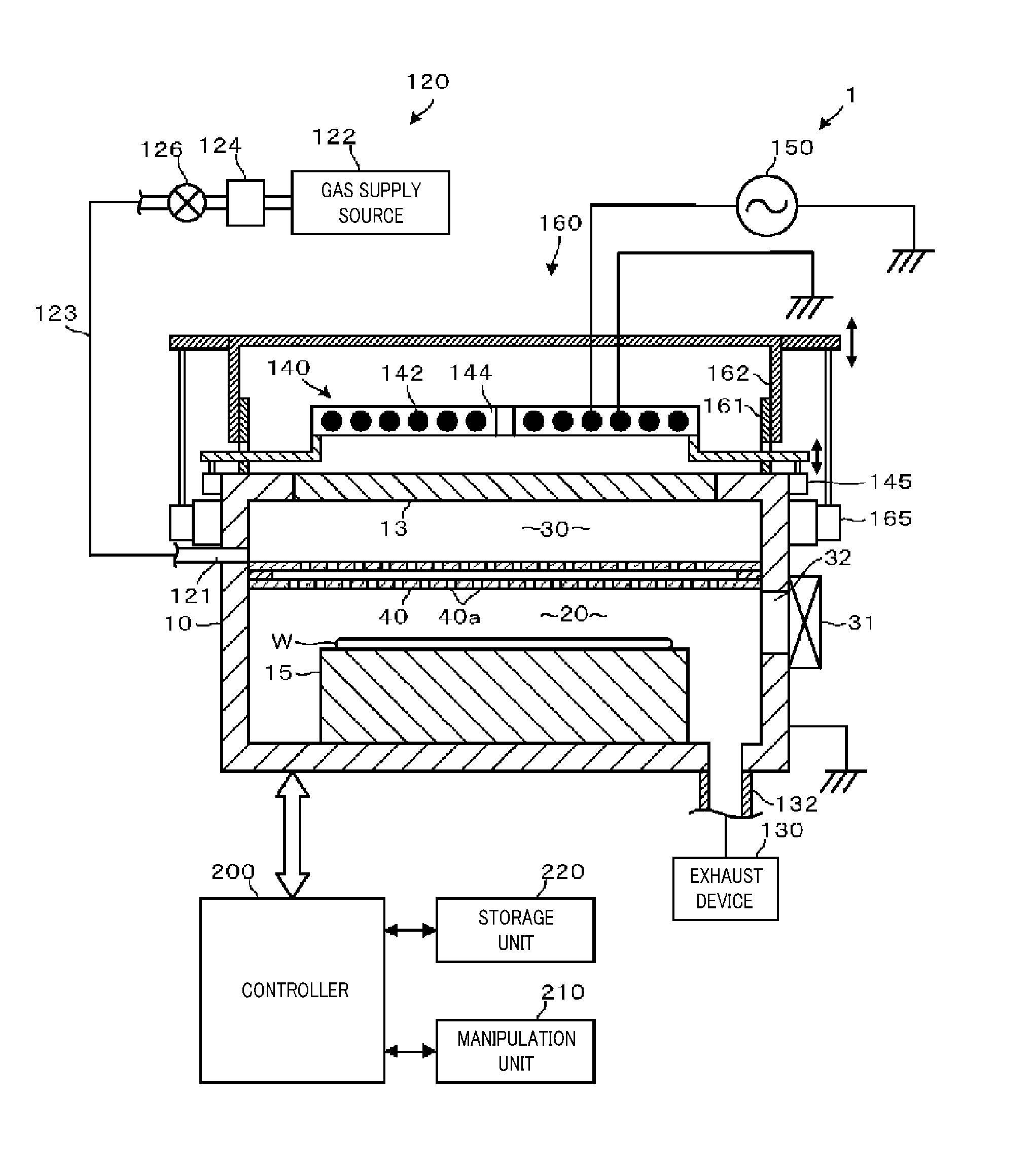
[0024]FIG. 1 schematically illustrates a configuration of a plasma processing apparatus 1 in accordance with an illustrative embodiment. The configuration of the plasma processing apparatus 1 will be first explained. The plasma processing apparatus 1 includes a processing chamber 10. The processing chamber 10 has a surface made of, but not limited to, an anodically oxidized aluminum and has a substantially cylindrical shape. A mounting table 15 for mounting thereon a processing target substrate such as a semiconductor wafer W is provided at a bottom portion within the processing chamber 10. A non-illustrated electrostatic chuck or the like for attracting and holding the processing target substrate is provided on a substrate mounting surface of the mounting table 15.

[0025]A dielectric window 13 made of quartz as a silicon-containing member is provided at a ceiling of th...


PUM

PropertyMeasurementUnit
Dielectric polarization enthalpyaaaaaaaaaa

Abstract

A plasma processing apparatus in which a cleaning method is performed includes a plasma generating chamber, having a silicon-containing member, for generating therein plasma by exciting a processing gas; a plasma processing chamber communicating with the plasma generating chamber via a partition member; and a high frequency antenna, having a planar shape, provided at an outside of a dielectric window of the plasma generating chamber. The cleaning method includes exciting a hydrogen-containing processing gas into plasma in the plasma generating chamber, introducing hydrogen radicals in the plasma into the plasma processing chamber through the partition member, performing a plasma process on a processing target substrate by allowing the hydrogen radicals to act on the processing target substrate, unloading the processing target substrate, and removing silicon-based deposits generated in the plasma generating chamber by introducing a tetrafluoride (tetrafluoromethane) gas into the plasma generating chamber.

Description

CROSS-REFERENCE TO RELATED APPLICATION[0001]This application claims the benefit of Japanese Patent Application No. 2011-089348 filed on Apr. 13, 2011 and U.S. Provisional Application Ser. No. 61 / 479,624 filed on Apr. 27, 2011, the entire disclosures of which are incorporated herein by reference.FIELD OF THE INVENTION[0002]The present disclosure relates to a cleaning method of a plasma processing apparatus and also relates to a plasma processing method.BACKGROUND OF THE INVENTION[0003]Conventionally, in the field of manufacture of semiconductor devices, there is known a plasma processing apparatus that is configured to perform various processes such as a film forming process or an etching process on a substrate such as a semiconductor wafer.[0004]With regard to such a plasma processing apparatus, there is also known a technique for asking a resist or etching a film of a low dielectric constant by generating plasma of a hydrogen gas and acting hydrogen radicals in the plasma of the hy...

Claims


Application Information

Patent Timeline
IPC IPC(8): B08B7/00H01L21/3065
CPCH01J37/32853H01J37/321H01L21/3065
Inventor TAHARA, SHIGERUNISHIMURA, EIICHI
Owner TOKYO ELECTRON LTD
Why Eureka
Try Eureka