Systems and methods for improved waste gas abatement

a waste gas and combustive technology, applied in the direction of combustion types, separation processes, gaseous mixture working up, etc., can solve the problems of waste gas passing through the system untreated, the performance of the abatement system is limited, and the system is not suitable for waste gas treatment, so as to reduce the accumulation of deposition products

Active Publication Date: 2018-09-13
ALZETA
View PDF2 Cites 5 Cited by
  • Summary
  • Abstract
  • Description
  • Claims
  • Application Information

AI Technical Summary

Benefits of technology

[0009]Among the various aspects of the present disclosure are systems and methods for providing efficient and controlled combu

Problems solved by technology

As these gases are processed by a waste gas abatement system to reduce environmental impact, silicon-containing gas-phase molecules react to form solid deposits that may, for example, block the flow of the waste stream and may thus limit the performance of the abatement system.
Such accumulation of particulate matter can disrupt proper mixing and reaction of waste and fuel gases, resulting in the failure of the abatement system to treat the perfluorocarbon gases and thus allowing waste gases to pass through the system untreated.
Such a process, however, is a costly solution that both interrupts manufacture of the semiconductor product and requires cumbersome safety protocols to prevent exposure of personnel to hazardous waste gases.
This approach requires the exposure of the mechanical components to high-temperature corrosive gases, reducing both mechanical strength and material thickness resulting in early failure of the device.
While this approach may ser

Method used


Image

  • Systems and methods for improved waste gas abatement
  • Systems and methods for improved waste gas abatement
  • Systems and methods for improved waste gas abatement

Examples


example 1

ild-Up on a 6×7 and 3×7 Burner with Exemplary Embodiment

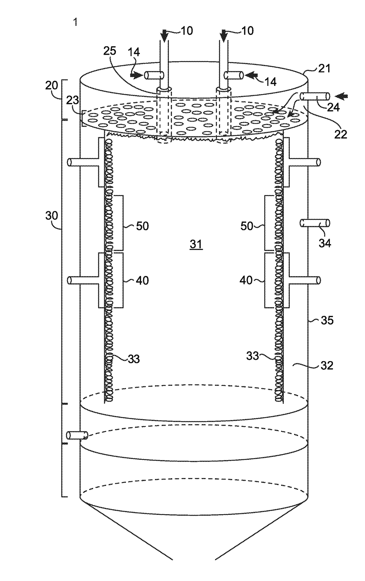
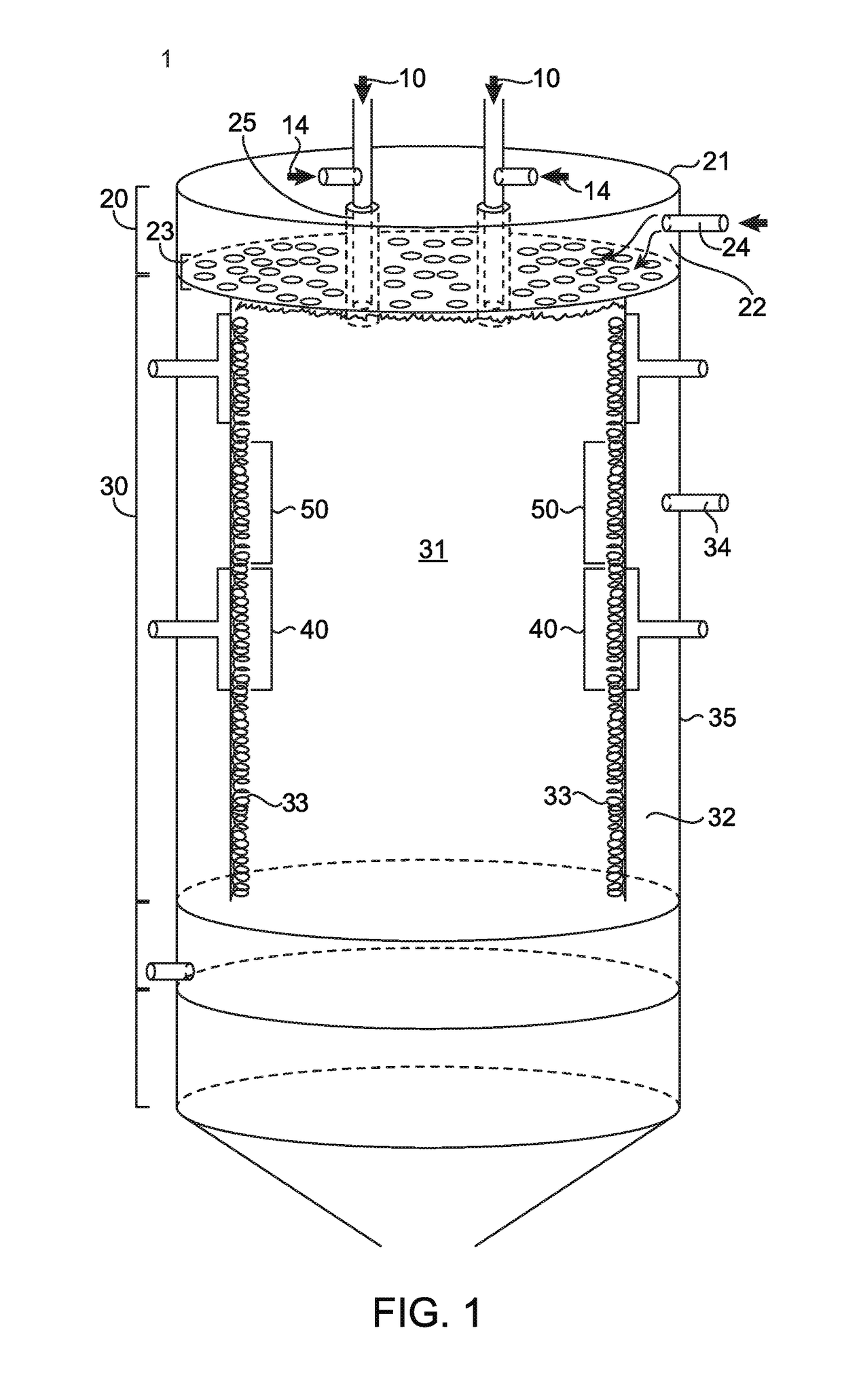
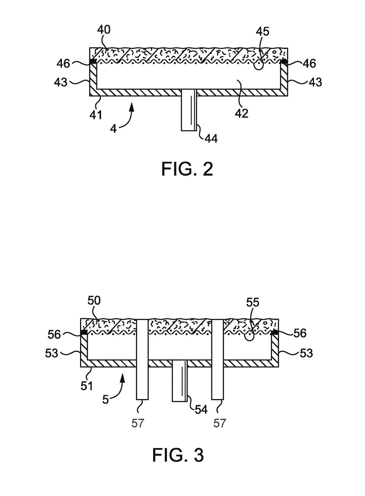
[0047]To investigate resistance to solid deposition, specifically from silica or other silicon containing solids, tests were conducted in a furnace having a similar configuration to FIG. 1. Second permeable interior wall (corresponding to 33 in FIG. 1) measured 7 inches inside diameter by 6 inches tall. The first permeable interior wall (corresponding to 23 in FIG. 1) was a 7 inch disc to form the ceiling with six apertures 25 to convey waste gas into the reaction chamber 30. Each waste gas tube was supplied with gas streams containing 50 liters per minute of nitrogen. An additional 2 liters per minute of silane was supplied to one waste gas tube. Natural gas and excess air were supplied through the second permeable wall to assist in destruction of the waste gas and 50 liters per minute of clean dry air was supplied to the first permeable wall to repel silica produced in the reaction zone. After 6480 liters of silane were consu...

example 2

ild-Up on a 6×7 Burner without Exemplary Embodiment

[0048]A comparison test was done with the same reaction chamber as described in Example 1, except that the first permeable wall was replaced with a non-permeable refractory surface. After consumption of 2160 liters of silane at a flow rate of 2 liters per minute, more than 0.75 cubic inches of silica deposited on the non-permeable refractory surface and waste gas nozzle. The majority of the silica was observed as deposited at the base of the waste gas nozzle, forming a tubular structure of silica extending into the reaction zone as shown in FIG. 6. This amount of silica deposition would have a negative effect on the destruction efficiency of perfluorocarbons. From these tests, it can be asserted that the invention reduces silica build up by more than 90%.

Example 3—CF4 and NF3 Testing on 6×7 Burner with Exemplary Embodiment

[0049]Additional tests were performed to ensure that the increased resistance to solid deposition provided by th...

examples 4 and 5

6×6 Burner with Exemplary Embodiment

[0055]After successful laboratory testing, further testing was done in two field installations operating on commercial semiconductor processes. The field sites chosen were third-party operated and produced large amounts of silica. Before the testing began, these sites had installed systems comprising reaction chambers similar to the configuration described in Example 2; there was no first permeable wall present, but instead there was a non-permeable refractory surface. In this configuration, the machine operators experienced frequent service shut downs due to solid deposition inside the reaction chamber, requiring them to open the unit and remove the solids. The permeable surfaces were installed and operated over the course of six months. During this time silica deposition inside the reaction chamber decreased significantly.

[0056]In the Example 4 field site, the throughput of wafers between required services increased on average by a factor of 3.4...


PUM


Abstract

The present disclosure generally relates to systems and methods for the combustive abatement of waste gas formed during the manufacture of semiconductor wafers. In particular, the systems described herein are capable of combusting air-polluting perfluorocarbons, including those having high greenhouse gas indexes such as hexafluoroethane (C2F6) and tetrafluoromethane (CF4), as well as particulate-forming silicon dioxide precursors, such as silane (SiH4) and tetraethoxysilane (Si(OC2H5)4, abbreviated TEOS), with greater efficiency and lower energy usage than prior abatement systems. More particularly, and in one preferred embodiment, the present disclosure is directed to a waste gas abatement system that utilizes a combination of non-combustible and combustible gases (or gas mixtures) for thermal combustion, which are directed through multiple permeable interior surfaces of a reaction chamber, efficiently combusting waste gas and preventing undesirable accumulation of solid particulate matter on the chamber surfaces.

Description

[0001]Aspects of the present disclosure generally relate to systems and methods for the combustive abatement of waste gas formed during the manufacture of semiconductor wafers. In particular, embodiments of the systems described herein are capable of combusting air-polluting perfluorocarbons, including those having high greenhouse gas indexes such as hexafluoroethane (C2F6) and tetrafluoromethane (CF4), as well as particulate-forming gases, such as silane (SiH4) and tetraethoxysilane (Si(OC2H5)4, abbreviated TEOS), with greater efficiency and lower energy usage than prior abatement systems. More particularly, and in one preferred embodiment, the present disclosure is directed to a waste gas abatement system that utilizes a combination of non-combustible and combustible gases (or gas mixtures) for thermal combustion, which are directed through multiple permeable interior surfaces of a reaction chamber.[0002]Fluorocarbon gases such as hexafluoroethane and tetrafluoromethane are global...

Claims


Application Information

Patent Timeline
IPC IPC(8): F23G7/06F23G5/12F23G5/24
CPCF23G7/065F23G5/12F23G5/245F23G2204/103F23G2209/14C10G70/00B01D53/005B01D2257/2066B01D2257/553B01D2257/556B01D2258/0216Y02C20/30Y02P30/00F23G5/24F23C99/006F23D14/125F23D2212/201F23D2212/103F23D14/145
Inventor SILBERSTEIN, MICHAEL J.BARTZ, DAVID FREDERICK
Owner ALZETA
Why Eureka
Try Eureka