Positioning apparatus for actuator with wave gear device

a wave gear and actuator technology, applied in adaptive control, computer control, instruments, etc., can solve the problems of direct influence of compensation accuracy, steady-state errors of output shafts and vibrations, modeling errors, etc., to improve the settling time and smooth load shaft response

Active Publication Date: 2012-10-25
HARMONIC DRIVE SYST IND CO LTD +1
View PDF1 Cites 12 Cited by
  • Summary
  • Abstract
  • Description
  • Claims
  • Application Information

AI Technical Summary

Benefits of technology

[0019]According to the positioning apparatus of the present invention, it was confirmed that an improvement in settling time and a smooth load shaft response can be obtained in comparison with a conventional P-PI control system. According to the present invention, a robust control system can therefore be constructed to protect against control performance degradation due to nonlinear characteristics in the wave gear device.

Problems solved by technology

Moreover, an angular transmission error occurs in synchrony with the relative rotation of every constituent part due to machining and assembly errors of the gears, producing steady-state errors of the output shaft and vibrations during transitions (Non-patent Document 3).
However, this method is an FF compensation method that presupposes a model-base, and a problem therefore arises in that modeling errors are directly influenced by compensation accuracy.

Method used


Image

  • Positioning apparatus for actuator with wave gear device
  • Positioning apparatus for actuator with wave gear device
  • Positioning apparatus for actuator with wave gear device

Examples


Embodiment Construction

1. Overview of the Experimental Device

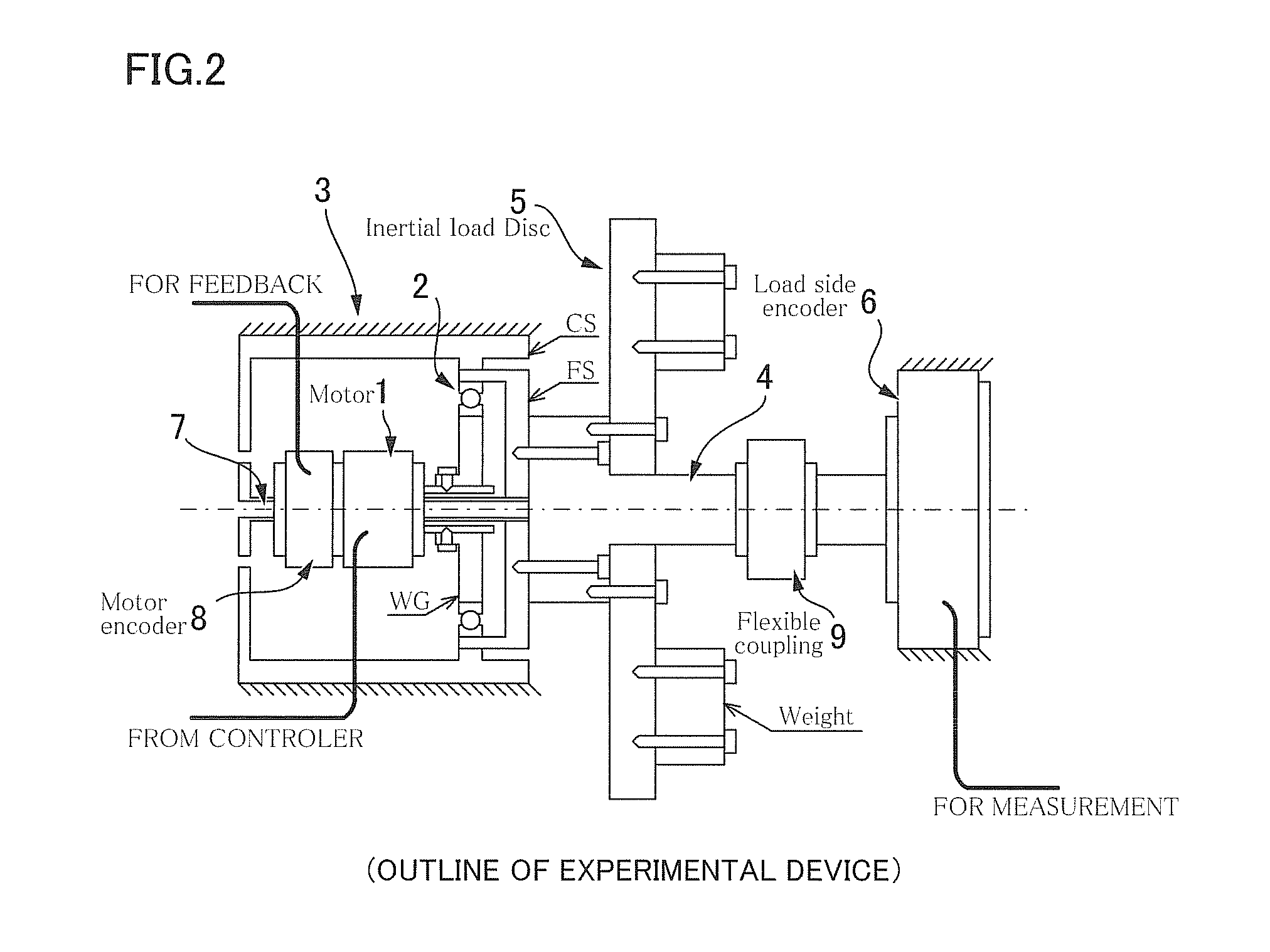
[0029]FIG. 2 is an explanatory view showing an example of a schematic configuration of an experimental device, which is the controlled object of the present invention, and the parameters thereof are shown in Table 1. An actuator 3 that includes a wave gear device 2 as a reduction gear in a motor 1 is the controlled object in the present invention. A full closed-loop control system is configured so that a load disk 5 and a load shaft encoder 6 are added to a load shaft 4 on the output end-side of the wave gear device 2, and motor shaft angle information from a motor shaft encoder 8 attached to a motor shaft 7 and load shaft angle information from the load shaft encoder 6 are provided as feedback to control the load shaft 4. A coupling 9 having sufficiently high rigidity is fastened between the load shaft 4 and the load shaft encoder 6 to prevent torsional vibration of the shaft.

TABLE 1Parameters for Experimental DeviceGear ratio (N)50Number of te...


PUM


Abstract

In a positioning apparatus for an actuator, a sliding mode controller for compensating for nonlinear characteristics of a wave gear device of the actuator generates a control input u to a controlled object, based on a position command θ1* and a state variable x for expressing the controlled object. The controlled object is defined in the following formula.
{dot over (x)}=Ax+Bu+Eθl*
y=Cx
The switching surfaces of the sliding mode control system are defined by a variable S expressed in the following formula.
S=BTP
The control input u is the sum of the linear-state feedback control term ul and the nonlinear control input unl
u=ul+unl=-(SB)-1(SAx+SEθl*)-k(SB)-1σσσ=Sx,
where σ is the switching function, and k is the switching gain.

Description

TECHNICAL FIELD[0001]The present invention relates to a positioning apparatus for an actuator configured so that the output rotation of a motor is reduced by a wave gear device and outputted from a load shaft. More specifically, the present invention relates to a positioning apparatus for an actuator provided with a wave gear device in which compensation for nonlinear characteristics is performed by sliding mode control in order to construct a robust control system to protect against the degradation of positioning control performance of the load shaft due to nonlinear characteristics of the wave gear device.BACKGROUND ART[0002]As shown in FIG. 1, typical wave gear devices are constructed of three fundamental components referred to as a circular spline CS (hereinafter also referred to as a “CS”) which is a ring-shaped rigid body having teeth carved into the inner circumference of the ring; a flexspline FS (hereinafter also referred to as an “FS”) which is a thin cup-shaped component ...

Claims


Application Information

Patent Timeline
Patent Type & Authority Applications(United States)
IPC IPC(8): G05B15/02
CPCG05B13/041
Inventor OKITSU, YOSHIFUMIYAMAMOTO, MASAFUMIKATO, YUKIIWASAKI, MAKOTO
Owner HARMONIC DRIVE SYST IND CO LTD
Why Eureka
Try Eureka