Vaned filtering element

a filter element and filtering technology, applied in nuclear elements, greenhouse gas reduction, separation processes, etc., can solve the problems of high head loss, high cost, and high cost of recirculation of fluid, so as to reduce the restriction of flow, reduce the thin-bed effect, and design compact

Active Publication Date: 2012-11-01
ATOMIC ENERGY OF CANADA LIMITED
View PDF5 Cites 24 Cited by
  • Summary
  • Abstract
  • Description
  • Claims
  • Application Information

AI Technical Summary

Benefits of technology

[0009]An object of the present invention is to provide a vaned filtering element. The present invention is an improvement to the Flat-Surface Fin design with the addition of vanes that result in a more compact design. The large increase in filtration surface area over a Flat-Surface fin is a significant advantage to reduce the thin-bed effect. The increased area reduces the restriction to flow entering the strainer by decreasing the water velocity through the screen and reducing the thickness of debris (because it is spread over a larger area). The resistance of this thin layer to flow entering the strainer is reduced with the larger screen area achieved by the vanes.

Problems solved by technology

Thin-bed debris can cause head losses high enough to threaten the functionality of emergency core cooling system (ECCS) sump recirculation pumps.
Thin-bed debris has occurred operationally at nuclear power plants and has been created during head-loss testing.

Method used


Image

  • Vaned filtering element
  • Vaned filtering element
  • Vaned filtering element

Examples


Embodiment Construction

Definitions

[0026]Unless defined otherwise, all technical and scientific terms used herein have the same meaning as commonly understood by one of ordinary skill in the art to which this invention belongs.

[0027]As used in the specification and claims, the singular forms “a”, “an” and “the” include plural references unless the context clearly dictates otherwise.

[0028]The term “comprising” as used herein will be understood to mean that the list following is non-exhaustive and may or may not include any other additional suitable items, for example one or more further feature(s), component(s) and / or ingredient(s) as appropriate.

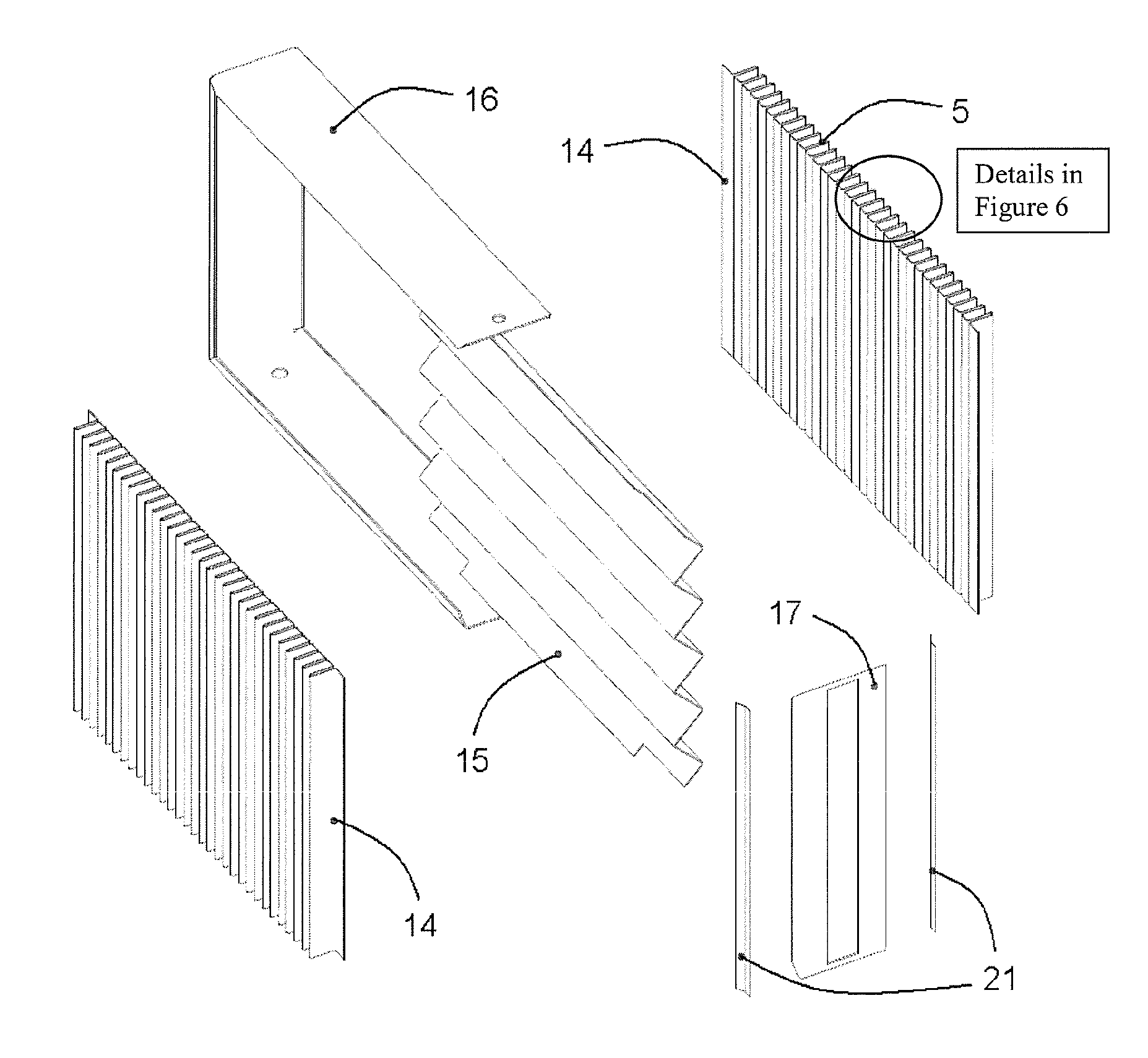
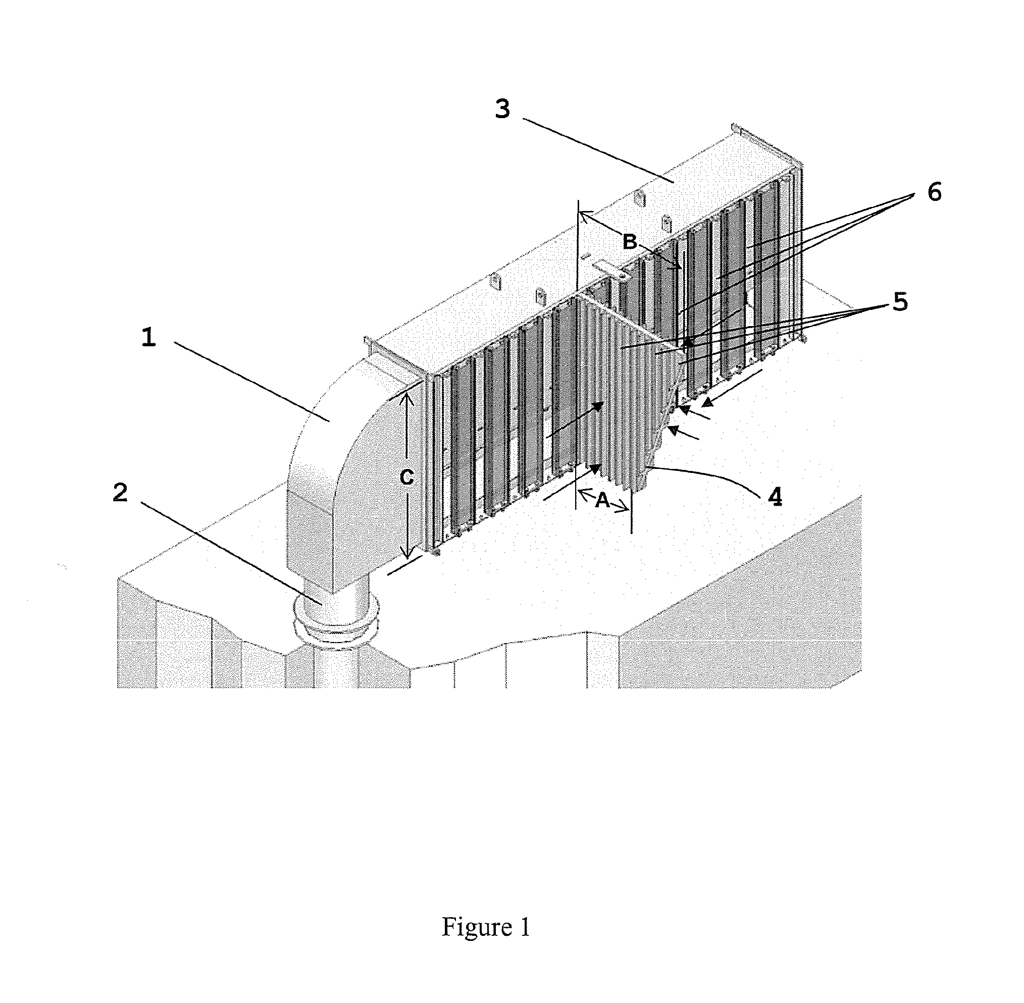
[0029]Briefly described, the present invention provides a vaned filter element comprising one or more fluid permeable screens formed from at least one layer of porous material that is folded into a plurality of hollow vanes extending outwardly from the outer surface of the each of the one or more fluid permeable screens. The vaned filtering element of the present i...


PUM

PropertyMeasurementUnit
sizeaaaaaaaaaa
thicknessaaaaaaaaaa
heightaaaaaaaaaa

Abstract

The present invention relates to filters used to remove debris from water being sucked into a piping system. It has particular application for use in nuclear power plants, which, after a loss of coolant accident, must pump cooling water back into the reactor core from a collection sump. This water may contain various types of debris that must be removed before the water is sent back into the reactor cooling system. Filtering of the debris is realized with the component known as “strainers”. There are restrictions on the space available for installing strainers. The vaned filtering element, for example a vaned fin, of the present invention is designed to reduce the space required for strainer installation by increasing strainer surface area per unit volume, while maximizing the quantity of debris that can be filtered from the water.

Description

FIELD OF THE INVENTION[0001]The present invention pertains generally to the field of fluid recirculation systems incorporating suction strainers. More particularly, the present application pertains to strainers used to remove debris from water being sucked into a piping system, such as in nuclear power plants.BACKGROUND[0002]A critical function of Emergency Core Cooling Systems (ECCS) and other recirculation systems of nuclear power plants is to move fluids quickly and in large volumes to critical areas of the nuclear power plant in the event of accidents and emergencies. Integral to this critical function is the ability of strainers, filters, screens and other such devices associated with the systems to remove solids from the moving fluids while at the same time maintaining a sufficiently large volume of fluid flow.[0003]Nuclear plants have various safety systems to ensure that the nuclear fuel in the reactor core remains cooled in all credible accident scenarios. One such scenario...

Claims


Application Information

Patent Timeline
Patent Type & Authority Applications(United States)
IPC IPC(8): B01D29/00
CPCB01D29/07G21D1/04Y02E30/40G21C13/02G21C19/307B01D29/52B01D29/39Y02E30/30Y02E30/00B01D35/02B01D35/28B01D2201/127
Inventor HAQUE, ZIAULRHODES, DAVID BRUCEGAUDET, MICHEL
Owner ATOMIC ENERGY OF CANADA LIMITED
Why Eureka
Try Eureka