

Sorting Colloidal Particles Into Multiple Channels with Optical Forces: Prismatic Optical Fractionation
a technology of prismatic optical fractionation and colloidal particles, which is applied in the direction of laser details, masers, laboratory glasswares, etc., can solve the problems of insufficient understanding of how brownian particles find their way through such structured terrains, and the much-studied model continues to yield surprises
- Summary
- Abstract
- Description
- Claims
- Application Information
AI Technical Summary
Benefits of technology
Problems solved by technology
Method used
Image

Examples
example a
Mixed Silica Colloidal Particles
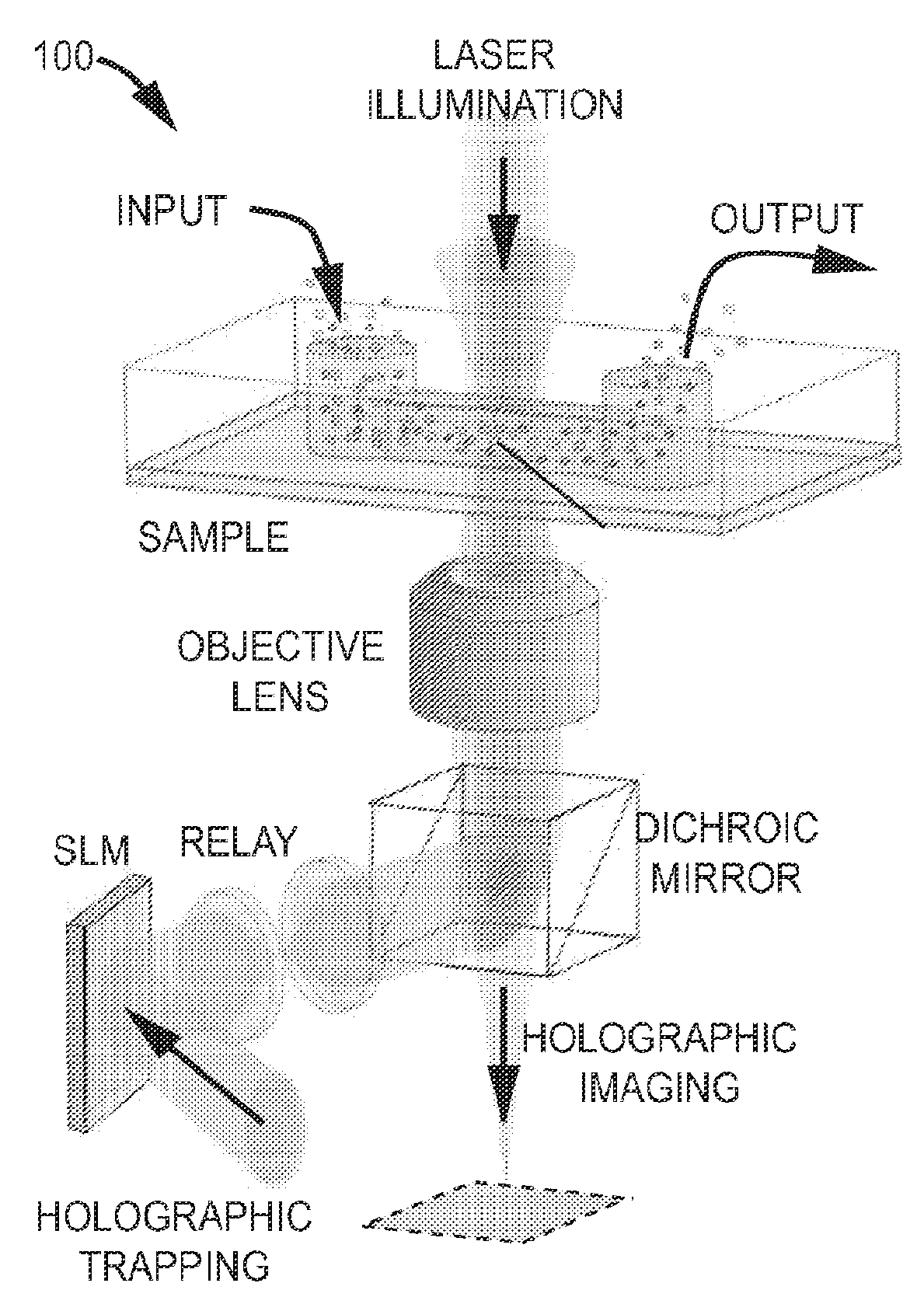
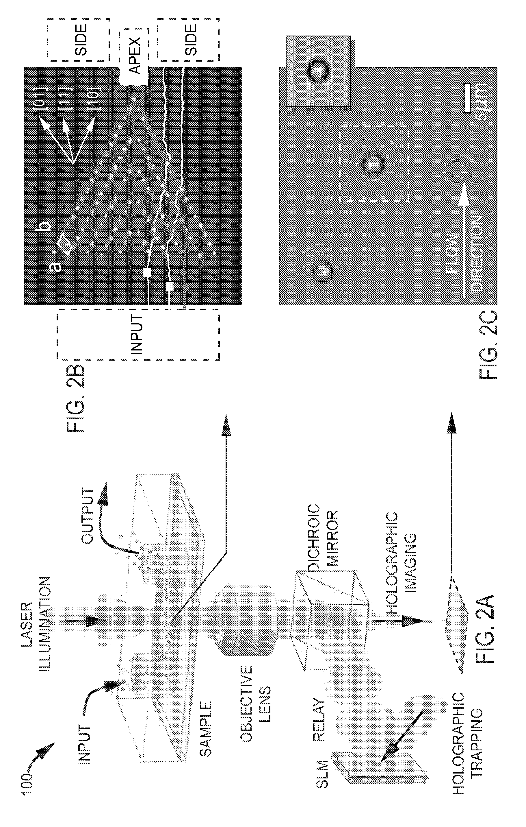
[0035]The data in FIGS. 3A(1)-3A(3) show results obtained with a mixture of two populations of monodisperse colloidal silica spheres, one 1.0 μm in diameter (Duke Scientific Catalog #8100, Lot #21024) and the other 1.5 μm diameter (Duke Scientific Catalog #8150, Lot #30158) at 1:1 stoichiometry. This mixed dispersion was owed at v=24±8 μm=s, through an optical trap array of the type shown in FIG. 2B with inter-trap separation of b=2.025 μm along the [10] direction and a=3.27 μm along the [01] direction. The [10] direction is inclined at Θ=30° with respect to the flow. The laser power per trap is estimated to be P=2.0±0.3 mW / trap based on imaging photometry of images such as the one in FIG. 2B.
[0036]The dense silica spheres tend to settle to the lower wall of the channel, as confirmed by three-dimensional holographic particle tracking. They thus approach the trap array more slowly than the peak flow rate along the channel's midplane because of the Pois...
example b
Monodisperse Silica Colloidal Particles
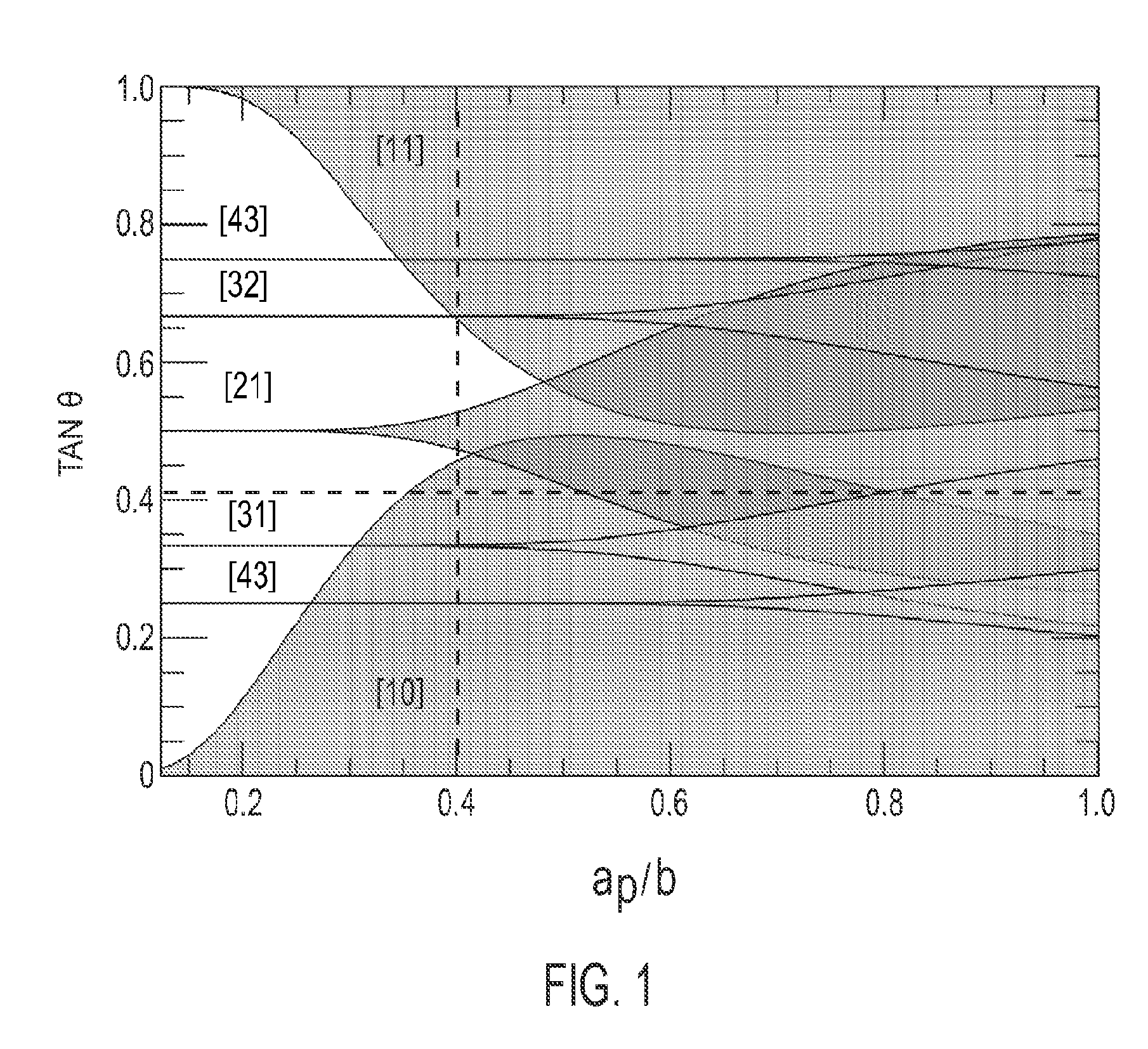
[0040]FIGS. 3B(1)-3B(3) show comparable results in the same optical tweezer array for a monodisperse sample of colloidal silica spheres with a nominal radius of 0.75±0.04 μm (PolySciences Catalog #24327, Lot #600424). Lorenz-Mie characterization reveals the actual sample-averaged radius to be somewhat smaller and more sharply distributed than the manufacturer's specification, with ap=0.715±0.021 μm . The measured refractive index of np=1.418±0.004 also is significantly lower than the nominal range for 1.43 to 1.46 for colloidal silica spheres, suggesting that these spheres are somewhat porous.
[0041]This sample was flowed with a slightly lower speed, v=22±5 μm / s, than in the previous example so that the predicted condition for locked-in transport along cuts through the middle of the sample's range of properties. The results in FIGS. 3B(1)-3B(3) show that smaller particles with lower refractive index are systematically deflected into the side are...
example c
Monodisperse Polystyrene Colloidal Particles
[0044]The data in FIGS. 3C(1)-3C(3) were obtained under comparable conditions with monodisperse samples of polystyrene spheres with a nominal radius of 0.50±0.02 μm (Duke Scientific Catalog #5100A, Lot #27527) and a nominal refractive index of 1.59 at 589 nm. Unlike silica spheres, polystyrene spheres are only 5% more dense than water. Consequently, they fill the channel as the flow toward the array of traps. Their comparatively high refractive index, moreover, renders them more susceptible to radiation pressure and thus less strongly trapped by optical tweezers. Rather than being drawn by optical forces toward the cell's midplane, consequently, these spheres predominantly are pushed toward the upper glass wall and creep along the surface in the slowest part of the Poiseuille flow. To compensate for the observed axial displacement, we refocus the optical trap array so that the particles continue to pass through in the plane of best focus. ...
PUM
 Abstract
Description
Claims
Application Information