System and Method to Determine Slide Quality of a Digitized Microscope Slide

a microscope slide and slide quality technology, applied in the field of digital pathology, can solve the problems of time-consuming and labor-intensive manual review of each image for sufficient scan quality, out of focus scans, and introduction of scan-hardware related artifacts into images

Active Publication Date: 2012-11-01
LEICA BIOSYST IMAGING
View PDF5 Cites 26 Cited by
  • Summary
  • Abstract
  • Description
  • Claims
  • Application Information

AI Technical Summary

Benefits of technology

[0010]By analyzing the images based on complexity and spatial frequencies, an example embodiment described herein provides visual feedback on the quality of the whole slide by overlaying the image in the viewing so...

Problems solved by technology
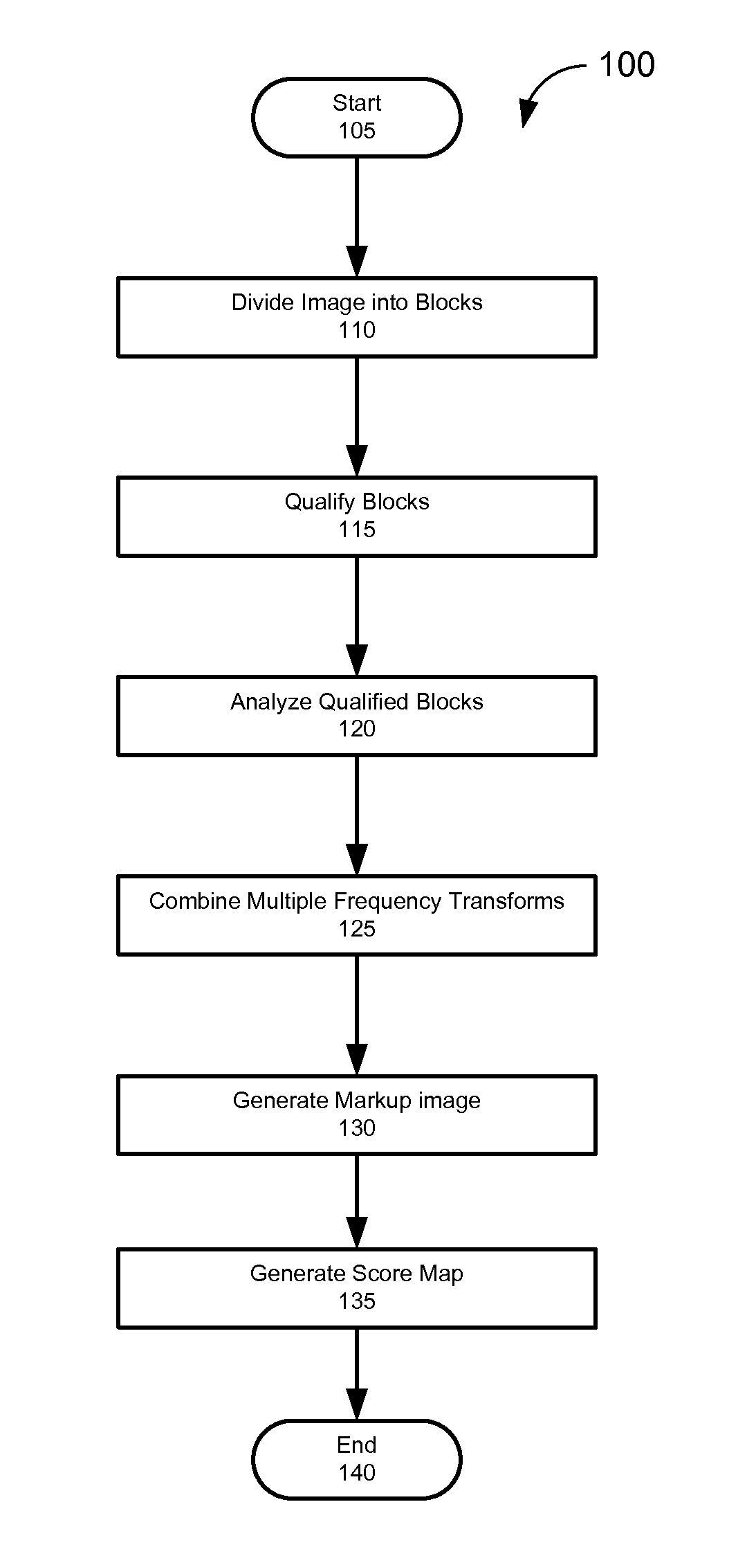
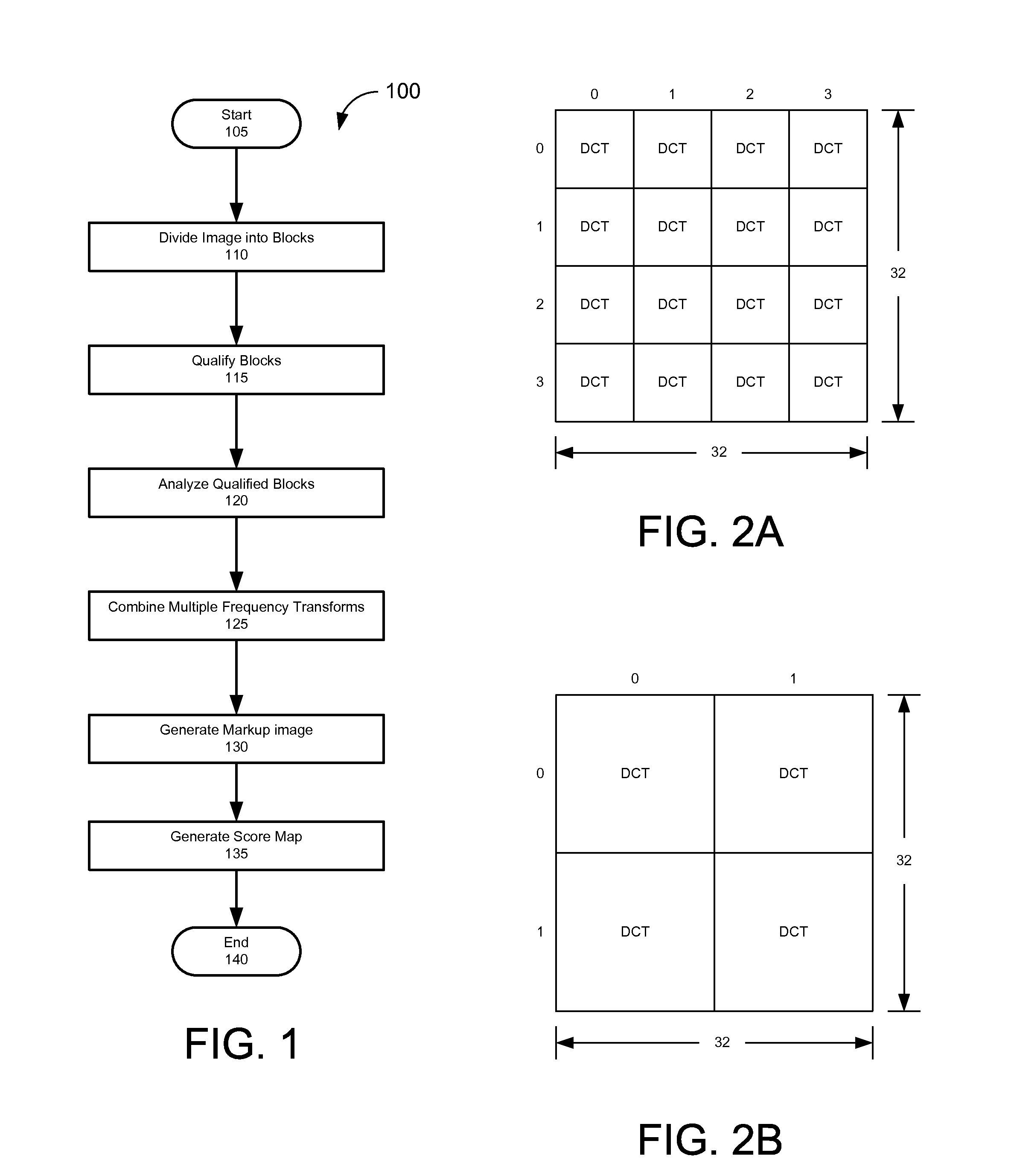
It is critical that the image is scanned without fault because the viewing software simply displays the captured digital slide and cannot re-focus the image or offer dynamic range adjustments.
Common problems that plague scanning software include, but are not limited to, out of focus scans and the introduction of scan-hardware related artifacts into images.
Manually reviewing each image for sufficient scan quality is time consuming because a given digital slide image may be very large (e.g., as large as 200K×100K pixels).
Additionally, in many cases only an expert may be able to properly judge variations in the quality of a digital slide and these judgments are highly subjective.
For example, scan artifacts can make distinct sub-cellular structures apparent in one s...

Method used


Image

  • System and Method to Determine Slide Quality of a Digitized Microscope Slide
  • System and Method to Determine Slide Quality of a Digitized Microscope Slide
  • System and Method to Determine Slide Quality of a Digitized Microscope Slide

Examples


second embodiment

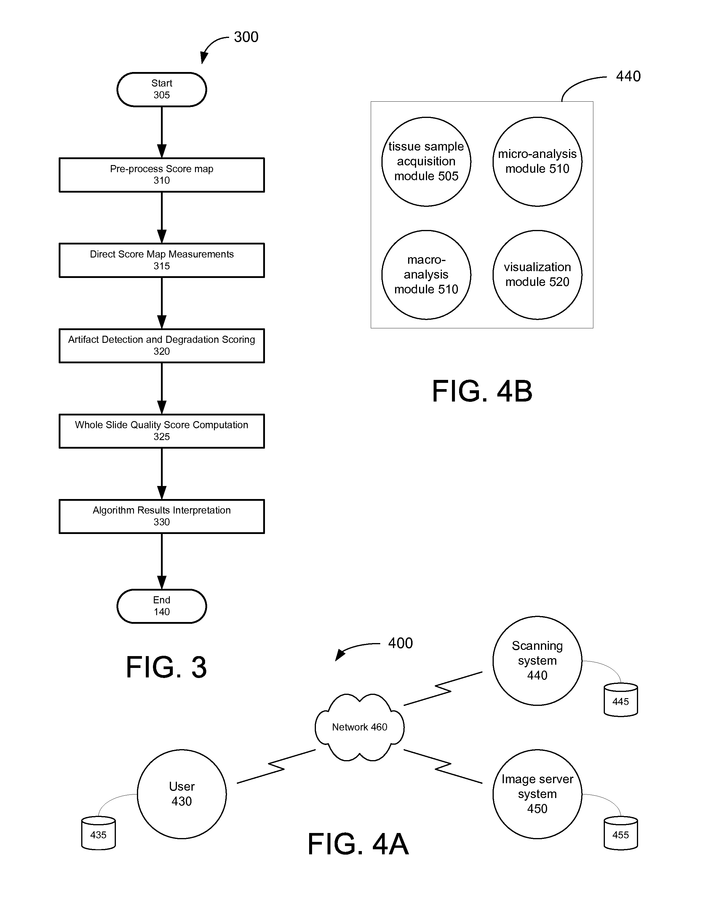
[0104]FIG. 5B illustrates a block diagram of an optical microscopy system 10 according to the present invention is shown. In this system 10, the scanner 11 is more complex and expensive than the currently preferred embodiment shown in FIG. 1. The additional attributes of the scanner 11 that are shown do not all have to be present for any alternate embodiment to function correctly. FIG. 2 is intended to provide a reasonable example of additional features and capabilities that could be incorporated into the scanner 11.

[0105]The alternate embodiment of FIG. 2 provides for a much greater level of automation than the presently preferred embodiment of FIG. 1. A more complete level of automation of the illumination system 28 is achieved by connections between the data processor 20 and both the light source 30 and the illumination optics 32 of the illumination system 28. The connection to the light source 30 may control the voltage, or current, in an open or closed loop fashion, in order to...

third embodiment

[0112]FIG. 5C is a block diagram of an optical microscopy system 10 according to the present invention. In this system 10, the scanner 11 is optimized for scanning fluorescent microscope samples. The additional attributes of the scanner 11 in this embodiment including the various software and hardware elements do not all have to be present for operation of the fluorescence scanner to function correctly. FIG. 3 illustrates a reasonable example of additional features and capabilities that could be incorporated into the scanner 11 for scanning fluorescent microscope samples.

[0113]FIG. 13 is a block diagram illustrating an example computer system 550 that may be used in connection with various embodiments described herein. For example, the computer system 550 may be used in conjunction with the digital pathology system and the computer and display monitors used in conjunction with the viewing software described herein. However, other computer systems and / or architectures may be used, as...


PUM


Abstract

A system that determines the quality of a digital microscope slide by analyzing digital slide images based on complexity and spatial frequencies. An example embodiment detailed in the application may provide visual feedback on the whole slide quality by overlaying the image with a color coded “heat map” of local area quality. A user provided with the overlap image may obtain both an absolute quality measurement for the whole image and quickly identity the quality variability within the slide.

Description

RELATED APPLICATION[0001]The present application is the U.S. national stage of international application number PCT / US2011 / 039173 filed 3 Jun. 2011, which claims priority to U.S. provisional patent application Ser. No. 61 / 396,971 filed 4 Jun. 2010, each of which is incorporated herein by reference in its entirety.BACKGROUND[0002]1. Field of the Invention[0003]The present invention relates to the field of digital pathology and more particularly relates to the assessment of image quality based on complexity and spatial frequencies and the presentation of said assessment using both visual and quantitative results.[0004]2. Related Art[0005]The cornerstone of pathology is the glass microscope slide with its biologic specimen. Traditionally, a pathologist used a conventional microscope to inspect the specimen. The pathologist would navigate the field of view by moving the slide underneath the microscope's lens and increase or decrease the field of view by selecting lenses of different mag...

Claims


Application Information

Patent Timeline
IPC IPC(8): G06K9/34
CPCG06T7/0004G06T2207/10056G06T2207/20021G06K9/00127G06T2207/30168H04N19/60H04N19/86G06T2207/30024G06V20/69
Inventor EICHHORN, OLEPERZ, CINDY
Owner LEICA BIOSYST IMAGING
Why Eureka
Try Eureka