Method of Making an Endoluminal Vascular Prosthesis

Active Publication Date: 2012-11-01
MEDTRONIC VASCULAR INC
View PDF6 Cites 54 Cited by
  • Summary
  • Abstract
  • Description
  • Claims
  • Application Information

AI Technical Summary

Benefits of technology

[0010]Embodiments hereof describe a method of forming an endoluminal prosthesis. In one embodiment, a flat sheet of woven material includes warp yarns and weft yarns interlaced at substantially right angles to each other. A graft material is cut from the flat sheet of woven material such that the graft material includes a graft material longitudinal axis and the warp yarns are disposed at an angle relative to the graft material longitudinal axis. The warp yarns and weft yarns are not parallel to or perpendicular to the graft material longitudinal axis. The graft

Problems solved by technology

An aneurysm is at risk of rupture resulting in extravasation of blood into, for example, the peritoneal cavity or into tissue surrounding the diseased artery.
While open surgery is an effective surgical technique in light of the risk of a fatal abdominal aortic aneurysm rupture, the open surgical technique suffers from a number of disadvantages.
The surgical procedure is complex, requires a long hospital stay, requires a long recovery time, and has a high mortality rate.
Although often referred to as stent grafts, these tubular

Method used


Image

  • Method of Making an Endoluminal Vascular Prosthesis
  • Method of Making an Endoluminal Vascular Prosthesis
  • Method of Making an Endoluminal Vascular Prosthesis

Examples


Embodiment Construction

[0017]With reference to the accompanying figures, wherein like components are labeled with like numerals throughout the figures, illustrative graft materials for endoluminal prostheses, and methods for making endoluminal prostheses are disclosed.

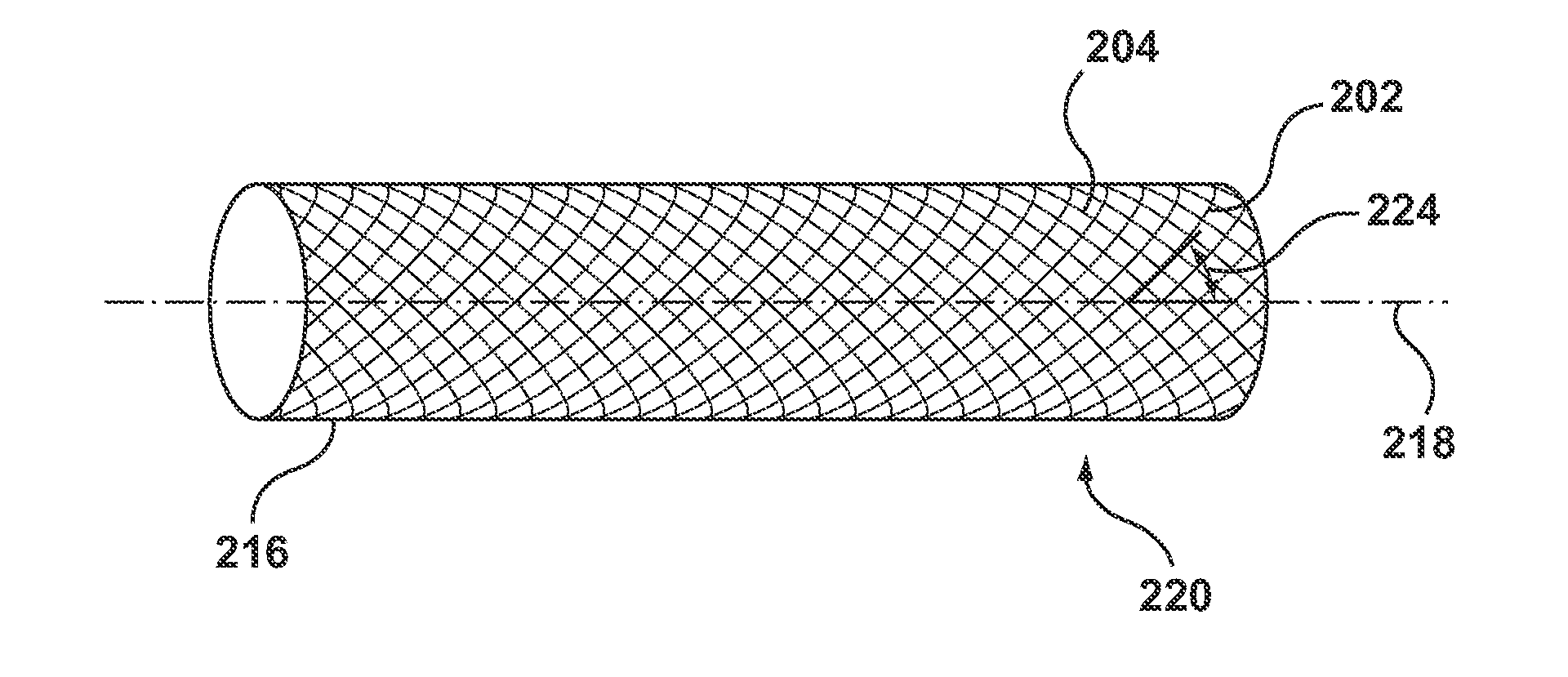
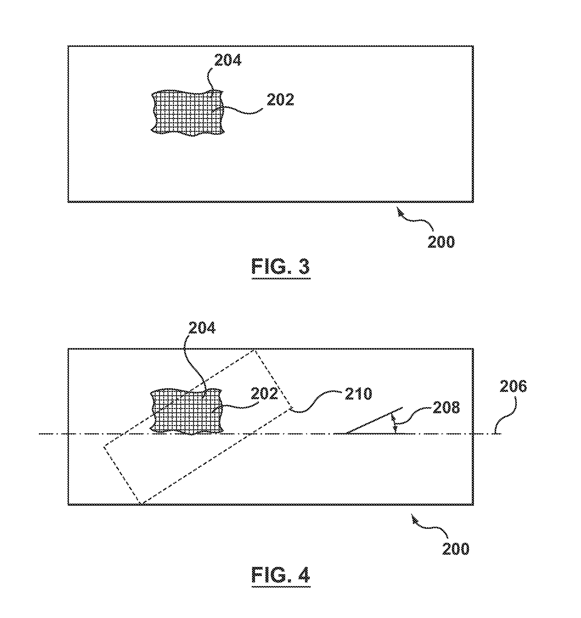
[0018]Referring now to the FIGS. 3-6, wherein components are labeled with like numerals throughout the several figures, an embodiment of a method of making a an endoluminal prosthesis 220 including a graft material 210 with warp yarns 202 disposed at an angle relative to a longitudinal axis 218 of the prosthesis 220 is disclosed. In particular, as shown in FIG. 3, a woven sheet of material 200 is utilized. Woven sheet of material 200 may be made from yarns made from biocompatible materials known to those skilled in the art as suitable for use in an endoluminal prosthesis, including but not limited to yarns made from polyester, polytetrafluoroethylene (PTFE), polypropylene, stainless steel, or nitinol. Woven sheet of material 200 consists of ...


PUM

PropertyMeasurementUnit
Angleaaaaaaaaaa
Angleaaaaaaaaaa
Angleaaaaaaaaaa

Abstract

A flat sheet of woven material includes warp yarns and weft yarns interlaced at substantially right angles to each other. A graft material is cut from the flat sheet of woven material such that the graft material includes a graft material longitudinal axis and the warp yarns are disposed at an angle relative to the graft material longitudinal axis. The warp yarns and weft yarns are not parallel to or perpendicular to the graft material longitudinal axis. The graft material is formed into the shape of an endoluminal prosthesis, such as by rolling opposing edges towards each other and securing the opposing edges to each other. The endoluminal prosthesis thus includes warp yarns disposed at an angle relative to the prosthesis longitudinal axis.

Description

TECHNICAL FIELD[0001]This invention relates generally to a method of making a vascular prosthesis.BACKGROUND[0002]Vascular aneurysms are the result of abnormal dilation of a blood vessel, usually from disease or a genetic predisposition, which can weaken the arterial wall and allow it to expand. Aneurysms can occur in any blood vessel, but most occur in the aorta and peripheral arteries, with the majority of aneurysms occurring in the abdominal aorta. An aneurysm is at risk of rupture resulting in extravasation of blood into, for example, the peritoneal cavity or into tissue surrounding the diseased artery.[0003]Aneurysms, especially abdominal aortic aneurysms, are commonly treated in open surgery procedures in which the diseased vessel segment is bypassed and repaired with an artificial vascular graft. While open surgery is an effective surgical technique in light of the risk of a fatal abdominal aortic aneurysm rupture, the open surgical technique suffers from a number of disadvan...

Claims


Application Information

Patent Timeline
IPC IPC(8): A61F2/82B23K31/02B32B38/00B21D51/16B23P11/00
CPCA61F2/06A61F2/07A61F2002/061A61F2002/065Y10T29/49826A61F2/89A61F2002/075Y10T156/1002A61F2240/001D03D3/02D10B2331/04D10B2101/20D10B2321/022D10B2509/06D03D1/00D10B2321/042D03D15/67D03D15/283
Inventor BERTINI, TIMOTHY
Owner MEDTRONIC VASCULAR INC
Why Eureka
Try Eureka