Laser device with configurable intensity distribution

a laser device and intensity distribution technology, applied in semiconductor lasers, instruments, manufacturing tools, etc., can solve the problem that the intensity distribution cannot be switched to a different shape, and achieve the effect of dimming the single vcsel or subgroup, and large degree of freedom

Active Publication Date: 2012-11-08
TRUMPF PHOTONIC COMPONENTS GMBH
View PDF1 Cites 164 Cited by
  • Summary
  • Abstract
  • Description
  • Claims
  • Application Information

AI Technical Summary

Benefits of technology

[0029]In order to further influence the intensity distribution in the working plane, the optics may be designed such that a non sharp image of the intensity distributions in the near field of the VCSELs is formed in the working plane. This may be achieved by adapting the radii or distances of the micro lenses and yields a smeared out and smooth intensity distribution for the corresponding subgroup or array. This also allows further modifications of the normal top-hat intensity distribution.
[0030]The switching of the geometrical shape of the intensit...

Problems solved by technology

Furthermore, this intensity distribution can not be switched to a di...

Method used


Image

  • Laser device with configurable intensity distribution
  • Laser device with configurable intensity distribution
  • Laser device with configurable intensity distribution

Examples


Embodiment Construction

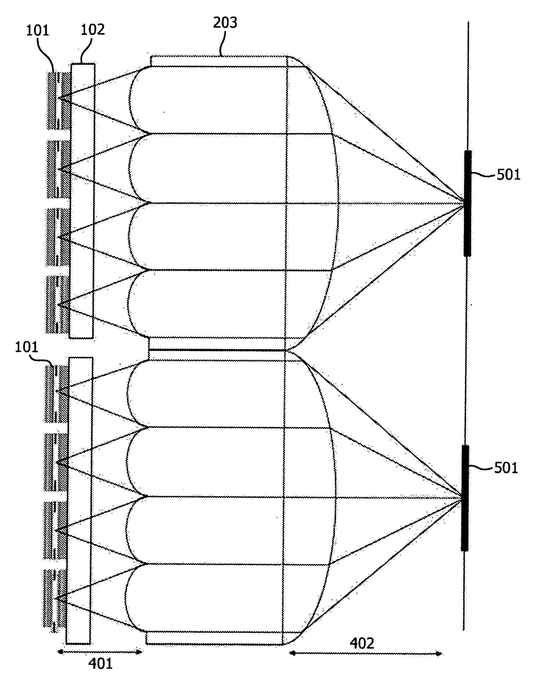
[0051]The intensity distribution of large area VCSELs in the near field can be set by the shape of the oxide aperture of the VCSEL, by the shape of the proton implantation, by the shape of the mesa or by the shape of the contact geometry of the VCSEL. FIG. 1 shows two examples of such an intensity distribution in the near field achieved with different shapes of the oxide aperture. On the left hand side a circular shape is achieved by a circular oxide aperture. The flower petal shaped intensity distribution on the right hand side is achieved by an oxide aperture having the same shape. The intensity profile of both examples is quite homogeneous and has sharp edges for the large angle Fourier modes, only slightly modulated by an interference pattern (not depicted in the figure). Using two large area VCSELs with oxide apertures of the above two shapes in the proposed laser device, it is possible to switch the intensity distribution in the working plane between these two shapes of the in...


PUM

PropertyMeasurementUnit
Poweraaaaaaaaaa
Diameteraaaaaaaaaa
Areaaaaaaaaaaa

Abstract

The present invention relates to a laser device comprising an array of several large area VCSELs (101) and one or several optics (201, 202) designed and arranged to image the active layers of the VCSELs (101) of said army to a working plane (501) such that the laser radiation emitted by the active layers of all VCSELs (101) or of subgroups of VCSELs (101) of the array superimposes in the working plane (501). The proposed laser device allows the generation of a desired intensity distribution in the working plane without the need of an optics specially designed for this intensity distribution or beam profile.

Description

FIELD AND BACKGROUND OF THE INVENTION[0001]The present invention relates to a laser device comprising an array of vertical cavity surface emission lasers (VCSELs). Vertical cavity surface emitting laser diodes are one of the most promising laser sources and offer many advantages compared to edge emitters, like addressable 2D-array arrangements, on-wafer testing and circular beam shapes.[0002]Small area oxide-confined VCSELs are known to emit Gauss modes. Higher output powers can be achieved by larger active areas, but the emission changes to distributions best described by Fourier modes. The near field of the laser beam fills the complete pumped active area or emission area of the laser, which is e.g. determined by the shape of the oxide-aperture, by the shape of the proton implantation, by the shape of the mesa or by the shape of the contact geometry of the laser diode. By appropriately setting these shapes it is thus possible to generate different shapes of intensity distribution ...

Claims


Application Information

Patent Timeline
IPC IPC(8): G02B27/12G02B27/10
CPCB23K26/0608B23K26/073H01S5/0624B41J2/451H01S5/423H01S2301/18H01S5/4012H01S5/0207H01S5/0267H01S5/02253
Inventor GRONENBORN, STEPHANMOENCH, HOLGER
Owner TRUMPF PHOTONIC COMPONENTS GMBH
Why Eureka
Try Eureka