Deep standby method and device for embedded system

Inactive Publication Date: 2012-11-08
ANYKA (GUANGZHOU) MICROELECTRONICS TECH CO LTD
View PDF13 Cites 8 Cited by
  • Summary
  • Abstract
  • Description
  • Claims
  • Application Information

AI Technical Summary

Benefits of technology

[0013](5) The method and device according to the embodiment of the invention writes a flag into the spare

Problems solved by technology

The existing embedded mobile device cannot automatically return to the previous interface when being powered on again after shutting down.
However, the standby technology can make the system return to the previous interface, which looks like shutdown.
In the case of the standby mode, there exists not only continuous resource consumption but also a certain amount of power consumption and equipment wear.
In this way, after a long tim

Method used


Image

  • Deep standby method and device for embedded system
  • Deep standby method and device for embedded system
  • Deep standby method and device for embedded system

Examples


Embodiment Construction

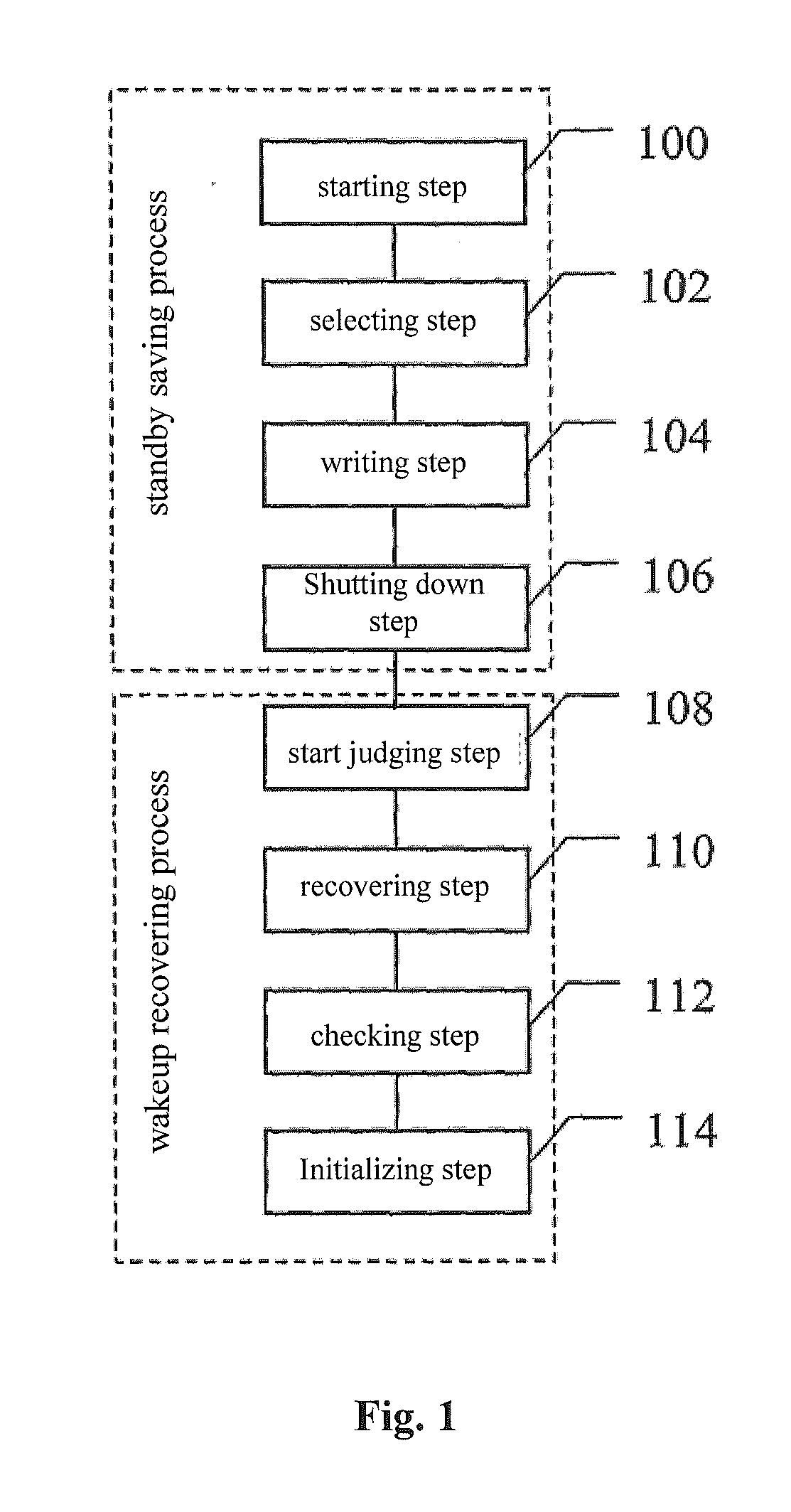
[0023]As shown in FIG. 1, a schematic flowchart of a deep standby method for an embedded system according to an embodiment of the invention is shown, which mainly includes: a selecting step 102, a writing step 104 and a shutting down step 106. In other embodiments, the method further optionally includes: a starting step 100, a startup judging step 108, a recovering step 110, a checking step 112, and / or an initializing step 114.

[0024]The method according to the embodiment can be generally divided into two processes, i.e. a standby saving process and a wake-up recovering process, as shown in FIG. 1. Steps involved in the two processes will be illustrated specifically hereinafter.

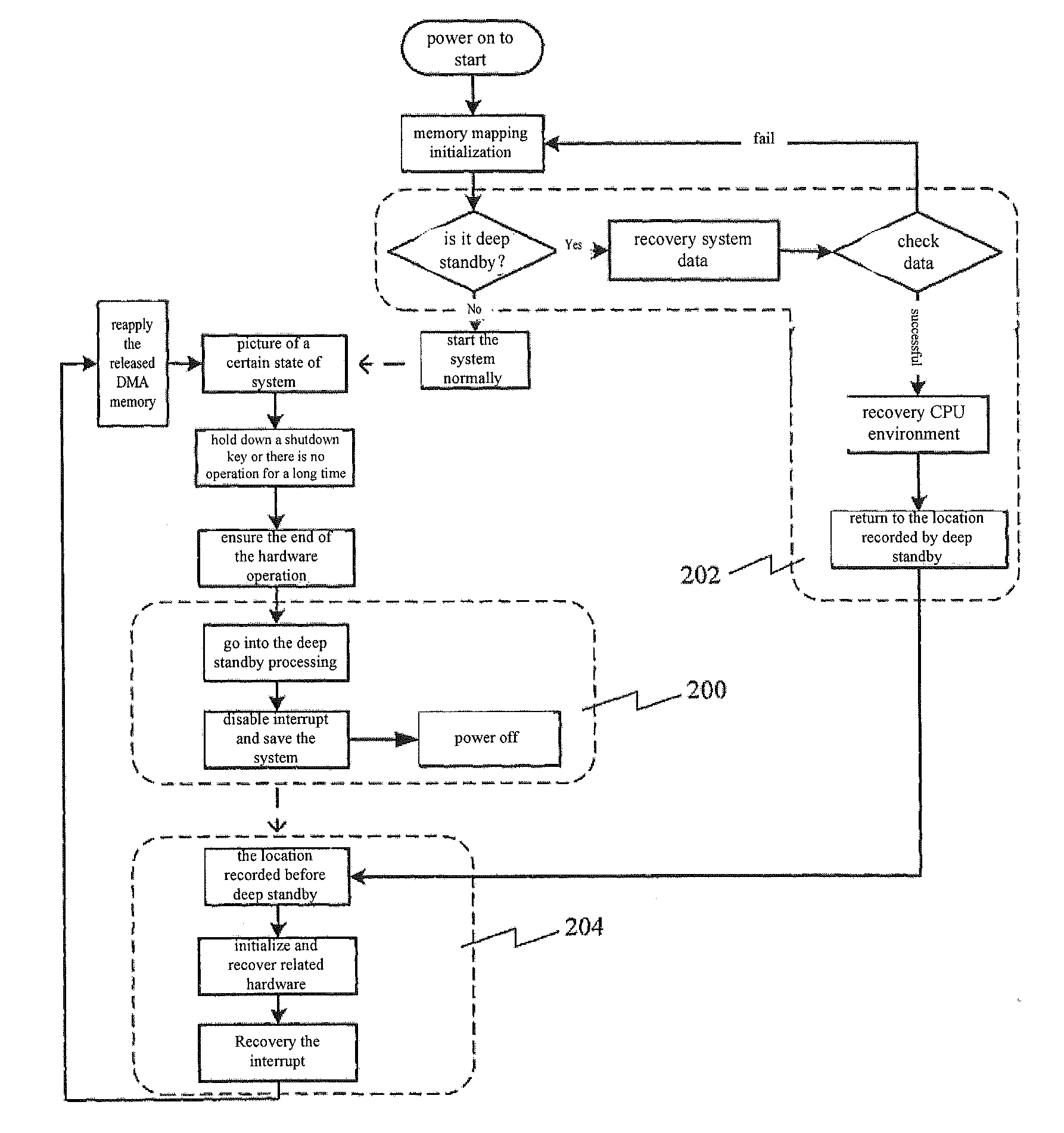
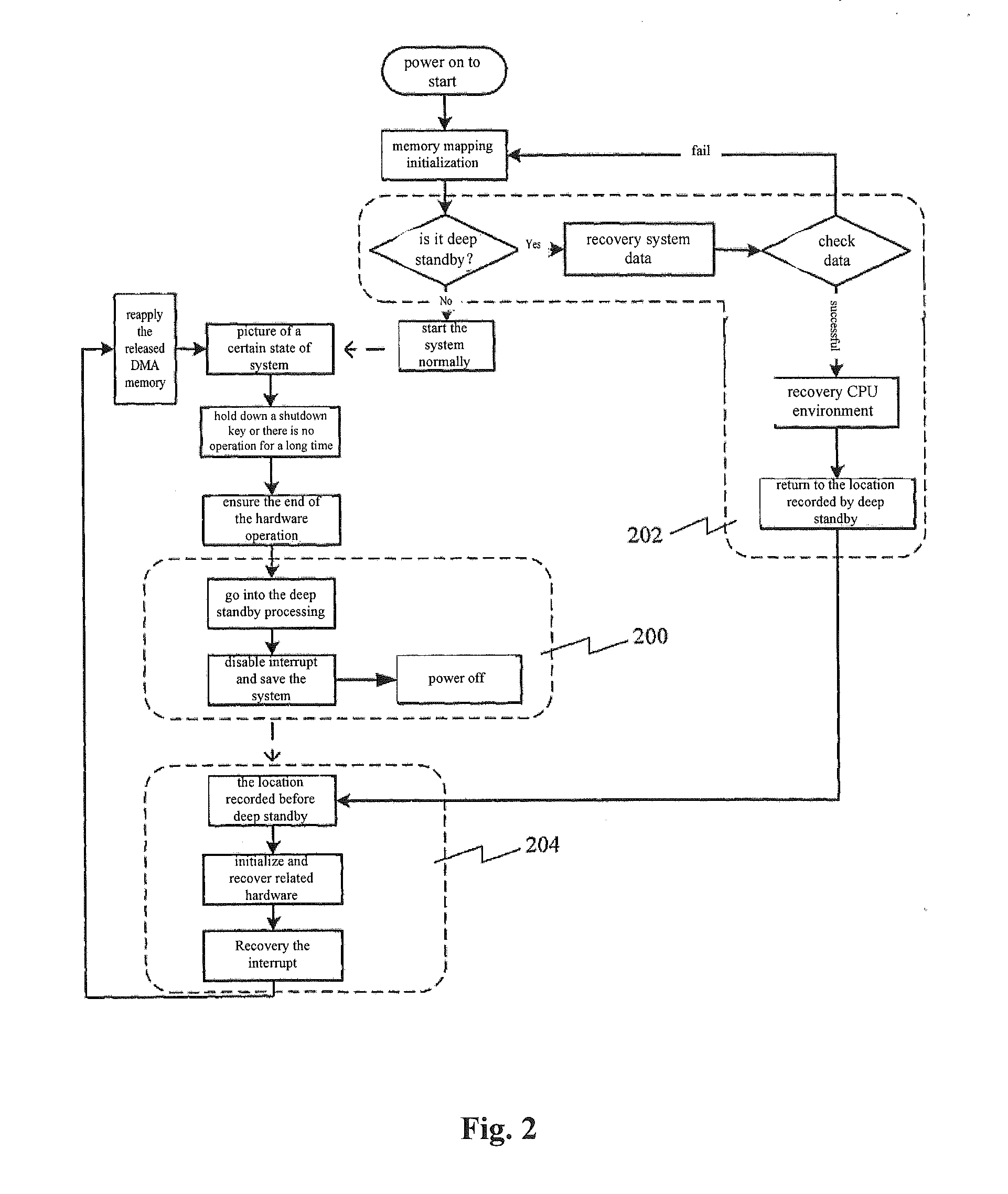
[0025]FIG. 2 shows a logic block diagram of implementing a deep standby method for an embedded system according to an embodiment of the invention. The implementation of the method according to the embodiment is divided into three processes: saving system data and CPU state (label 200 in Figure), recovering sys...


PUM


Abstract

A deep standby method and device for and embedded system is disclosed, wherein the method mainly includes: a selecting step for selecting an available data swap block from the data swap area of a non-volatile memory as a deep standby block; a writing step for writing the current system data and state of the CPU into the deep standby block, and writing a deep standby flag into the deep standby block; and a shutting down step for making the system off to fall into a deep standby.

Description

FIELD OF THE INVENTION[0001]The invention relates to a method and a device for switching a system into standby, and particularly to a method and a device for switching an embedded system into deep standby.BACKGROUND OF THE INVENTION[0002]At present, the use of embedded mobile devices becomes more and more popular, such devices are generally battery-powered, and therefore one of the most important features thereof is the demand for low power consumption. In order to save power, the embedded mobile devices often need to switch into a standby mode. The standby mode refers to: storing the state and data of the running programs into a special non-volatile memory; and when the system switches to this mode, cutting off the power supply of all parts except for the memory. Since the memory maintains the system data based on the electricity, the system can be recovered to the state before standby when waking up. This is the most widely used standby technology adopted by the existing embedded ...

Claims


Application Information

Patent Timeline
IPC IPC(8): G06F1/32
CPCG06F1/3206Y02B60/32G06F1/3234Y02D30/50
Inventor ZHAO, JUNHUAXU, PINGLUO, JIANHUAHU, NORMAN SHENGFA
Owner ANYKA (GUANGZHOU) MICROELECTRONICS TECH CO LTD
Why Eureka
Try Eureka