Semiconductor light source lighting circuit

a technology of semiconductors and light sources, applied in the direction of lighting apparatus, light sources, electroluminescent light sources, etc., can solve the problems of low power consumption, unnecessarily or inconvenient circuit size, and the large capacity of capacitors provided for maintaining the value of current in an analog manner, so as to reduce the size of the circuit

Active Publication Date: 2012-11-15
KOITO MFG CO LTD
View PDF1 Cites 22 Cited by
  • Summary
  • Abstract
  • Description
  • Claims
  • Application Information

AI Technical Summary

Benefits of technology

[0011]According to this aspect, the control circuit is able to digitally retain the magnitude of the drive current during the inactive state of the switching regulator.
[0012]According to the present invention, it is possible to reduce the circuit size while realizing the PWM light dimming.

Problems solved by technology

In recent years, vehicular lamps, such as headlamps and the like, use LEDs that are long in service life and low in power consumption, instead of conventional halogen lamps that have filaments.
However, generally, the capacitors provided for maintaining the value of current in an analog manner have relatively large capacity.
Therefore, there is a possibility of the size of the circuit becoming unnecessarily or inconveniently large

Method used


Image

  • Semiconductor light source lighting circuit
  • Semiconductor light source lighting circuit
  • Semiconductor light source lighting circuit

Examples


first embodiment

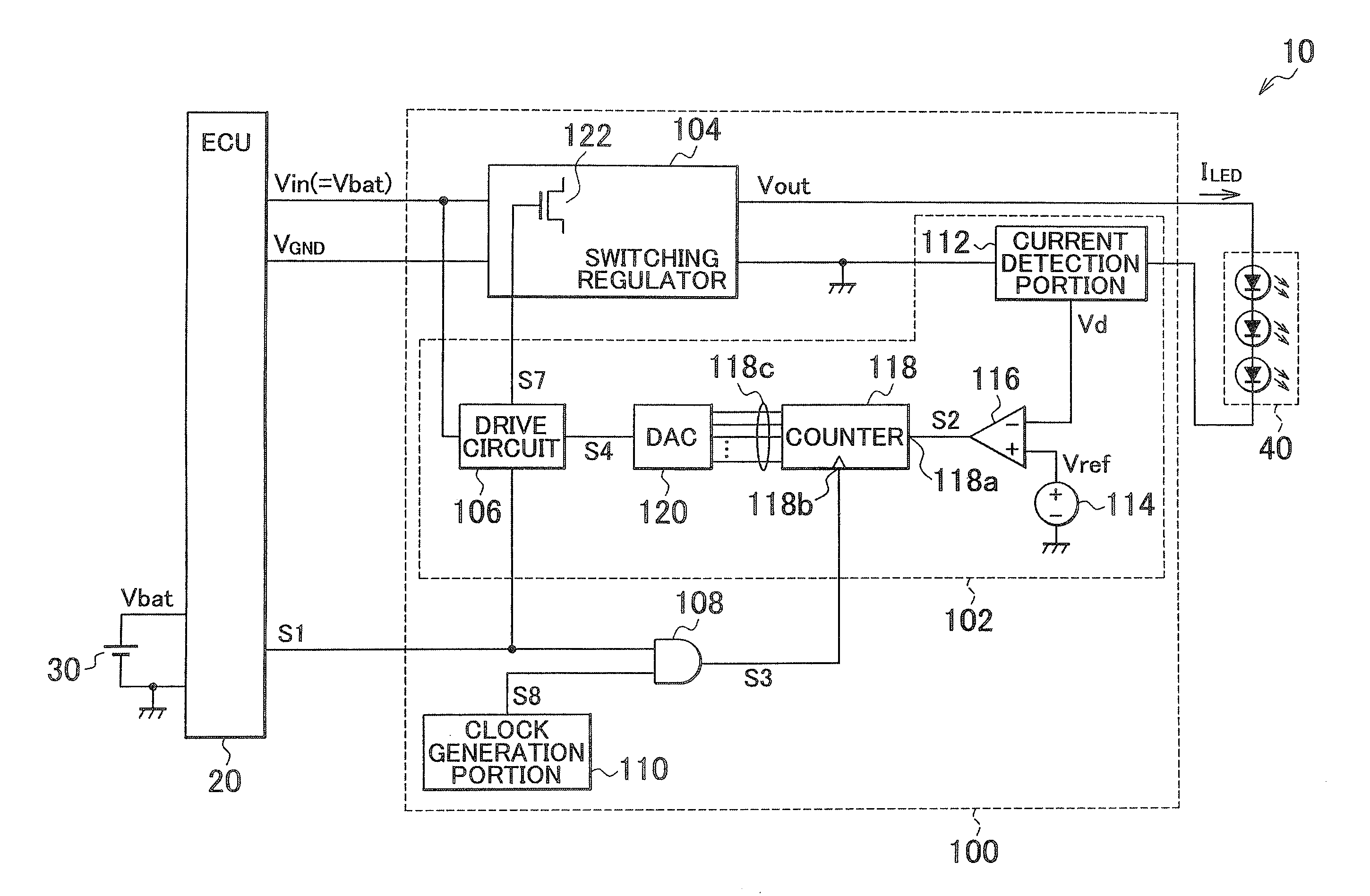
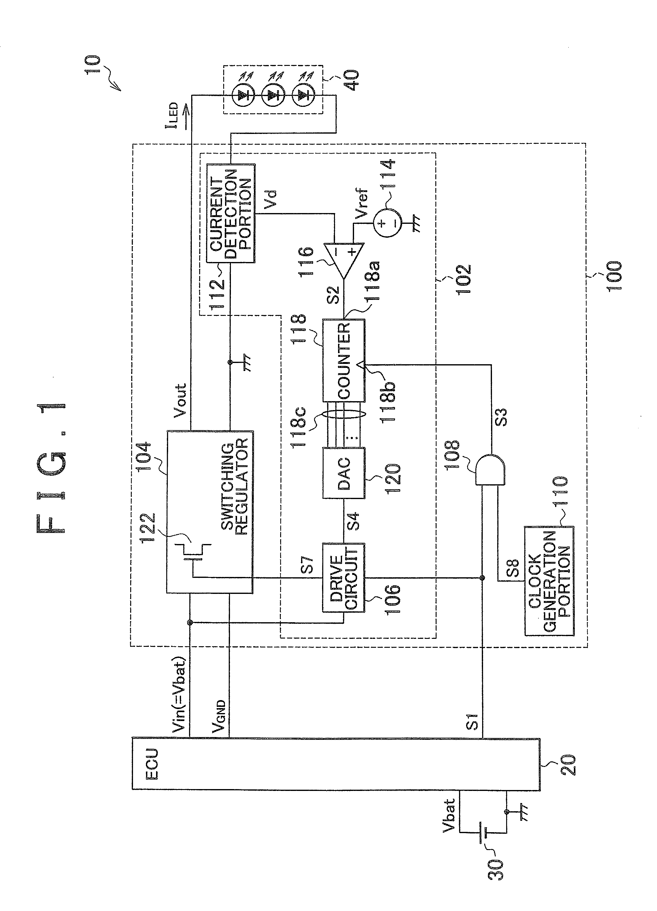
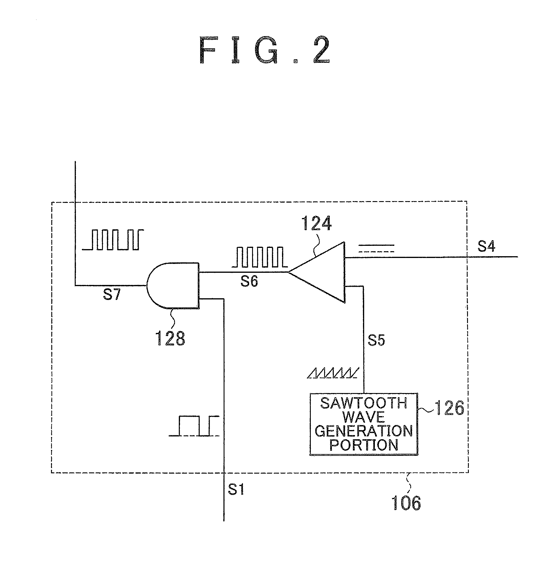
[0023]A semiconductor light source lighting circuit in accordance with a first embodiment of the present invention includes a switching regulator that produces a drive current that flows through a light emitting diode (LED) by using a switching element, and a control circuit that performs feedback control of turning on and off of the switching element so that the magnitude of the drive current approaches a target value. Furthermore, the semiconductor light source lighting circuit performs pulse width modulation (PWM) light dimming. Specifically, the degree of light emission from the LED is adjusted by the switching regulator repeatedly switching between an active state in which drive current is produced and an inactive state in which drive current is not produced. It is to be noted herein that control values, such as an error amount in the feedback control, and the like, are digitally retained from when the switching regulator is brought into the active state to when the switching r...

second embodiment

[0049]In the first embodiment, the engine control unit 20 generates the PWM light dimming signal S1, and supplies it to the semiconductor light source lighting circuit 100, and also supplies the semiconductor light source lighting circuit 100 with the input voltage Vin that is substantially constant regardless of the PWM light dimming signal S1. In this case, although not shown in FIG. 1, there generally arises a need to provide both the engine control unit 20 and the semiconductor light source lighting circuit 100 with interface circuits for sending and receiving the PWM light dimming signal S1. In the second embodiment, the use of the PWM light dimming signal S1 is not used, and the input voltage Vin is used instead to realize the PWM light dimming by turning the input voltage Vin on and off at the light dimming frequency f1. This makes it possible to omit one of the signal lines between the engine control unit and the semiconductor light source lighting circuit, and the need for ...


PUM


Abstract

A semiconductor light source lighting circuit includes a switching regulator that produces a drive current ILED with a switching element, and a control circuit that controls turning on and off of the switching element so that the magnitude of the drive current ILED approaches a target value. The control circuit includes an error comparator that compares the drive current ILED and the target value, an up/down counter that performs a counting operation, in which the control digital value is incremented or decremented based on the result of the comparison, a D/A converter that converts the control digital value into an analog duty ratio setting signal S4, and a drive circuit that controls the turning on and off of the switching element based on the signal S4. The up/down counter stops the counting operation when the switching regulator is brought into the inactive state.

Description

INCORPORATION BY REFERENCE[0001]The disclosure of Japanese Patent Application No. 2011-107177 filed on May 12, 2011 including the specification, drawings and abstract is incorporated herein by reference in its entirety.BACKGROUND OF THE INVENTION[0002]1. Field of the Invention[0003]The present invention relates to a semiconductor light source lighting circuit that lights a semiconductor light source such as a light emitting diode (LED) or the like.[0004]2. Description of Related Art[0005]In recent years, vehicular lamps, such as headlamps and the like, use LEDs that are long in service life and low in power consumption, instead of conventional halogen lamps that have filaments. The degree of light emission of an LED, that is, the brightness thereof, depends on the magnitude of electric current that flows through the LED. Therefore, when an LED is to be used as a light source, it is necessary to provide a lighting circuit for adjusting the current that flows through the LED. Such a l...

Claims


Application Information

Patent Timeline
Patent Type & Authority Applications(United States)
IPC IPC(8): H05B37/02H05B44/00
CPCH05B33/0851H05B45/10
Inventor KIKUCHI, SATOSHISHIOTSU, FUMINORINAMBA, TAKANORIITO, MASAYASU
Owner KOITO MFG CO LTD
Why Eureka
Try Eureka