Display Interface Circuit

a technology of interface circuit and display device, which is applied in the direction of electric digital data processing, instruments, and static indicating devices, etc., can solve the problems of mipi b>10/b> malfunction, particular difficulties in clock distribution, and inability to guarantee a reduction of clock latency

Inactive Publication Date: 2012-11-15
NOVATEK MICROELECTRONICS CORP
View PDF4 Cites 24 Cited by
  • Summary
  • Abstract
  • Description
  • Claims
  • Application Information

AI Technical Summary

Problems solved by technology

This poses particular difficulties for performing clock distribution in the MIPI 10.
Generally, circuit designers perform clock distribution via Clock Tree Synthesis (CTS) techniques to reduce clock skew between different components of the MIPI 10, but this does not guarantee a reduction in clock latency.
However, as the clock signal CLK increases in clock rate to accommodate high speed transmission requirements, the clock latency LTC may result in a hold time violation in the CLK_b, as shown in FIG. 2B, causing the MIPI 10 malfunction.

Method used


Image

  • Display Interface Circuit
  • Display Interface Circuit
  • Display Interface Circuit

Examples


Embodiment Construction

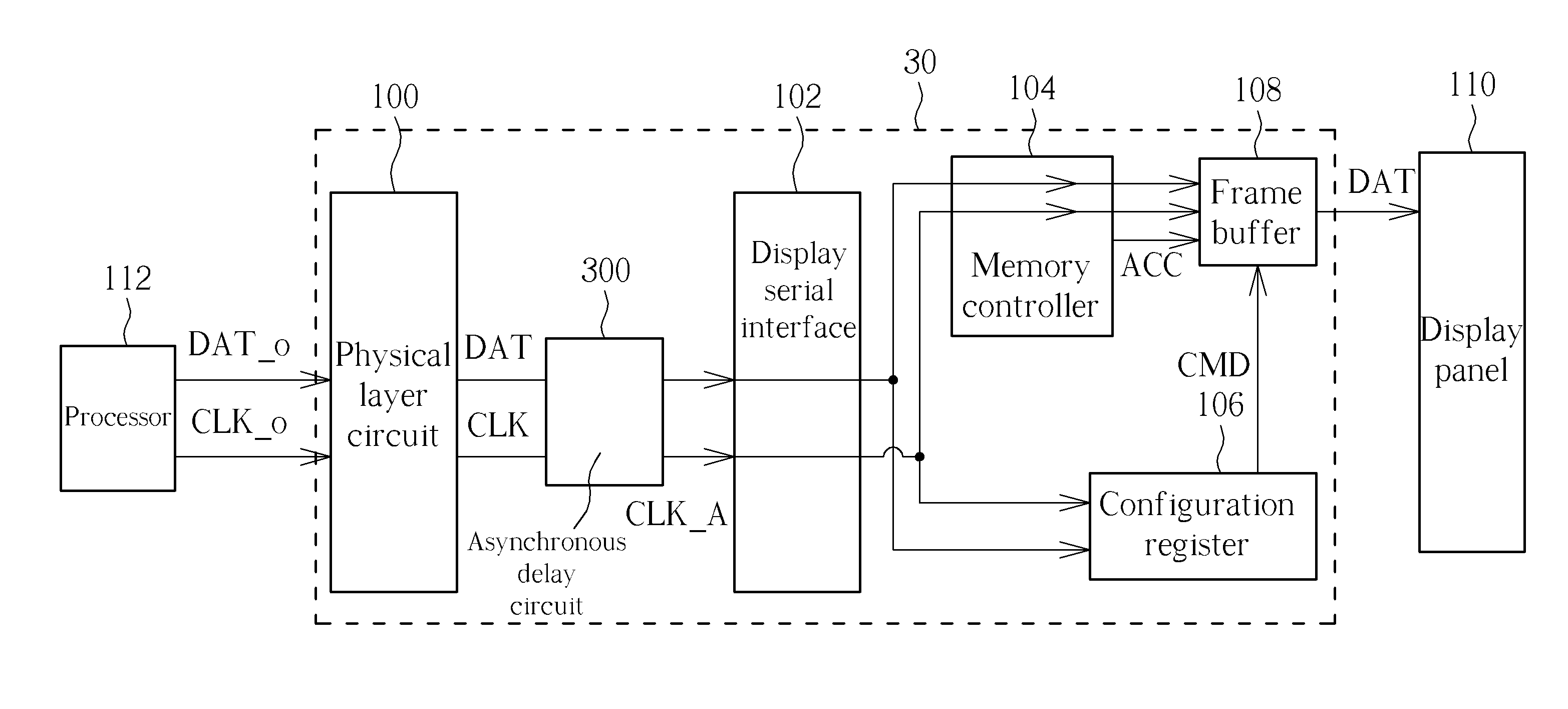
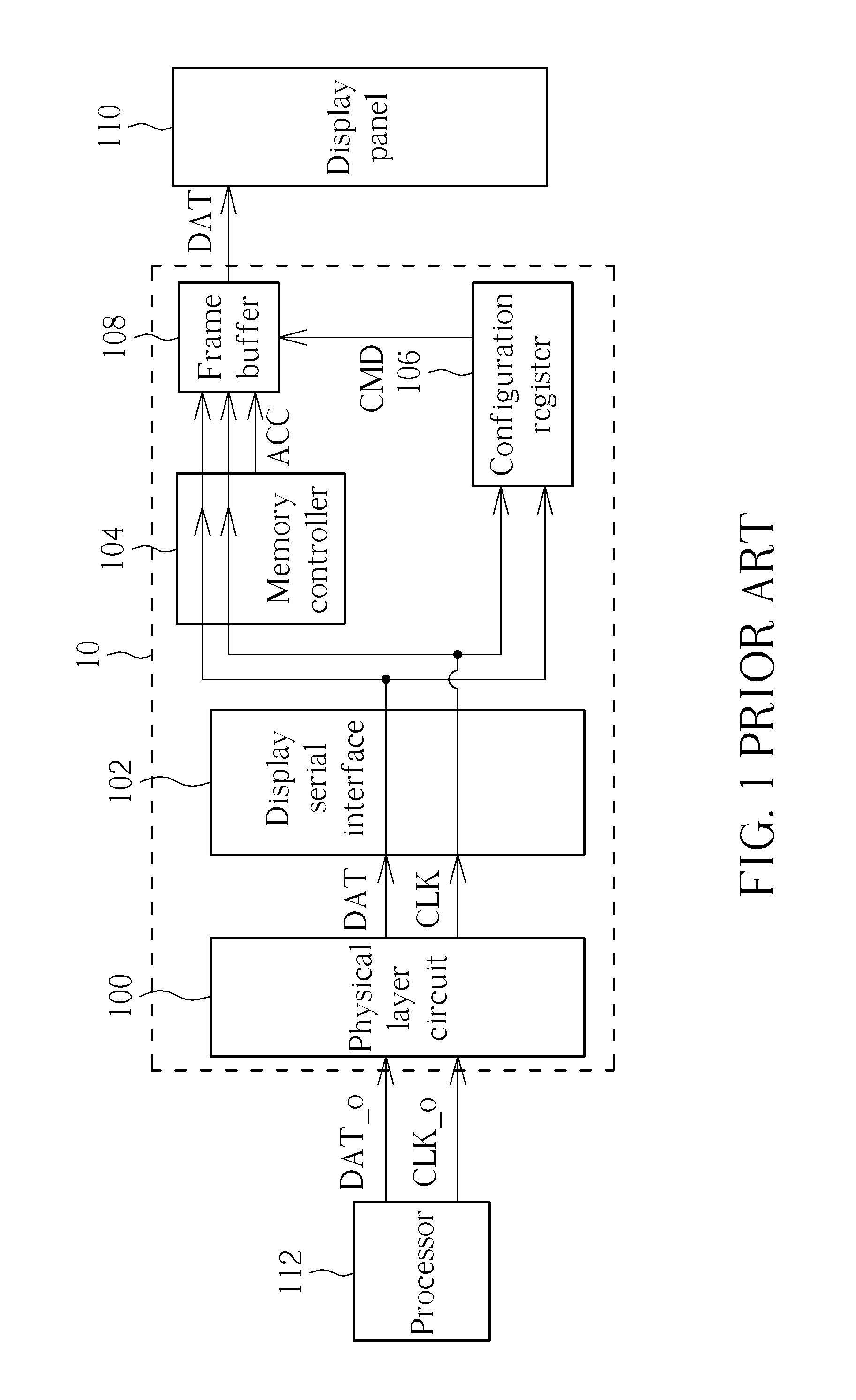
[0016]Please refer to FIG. 3, which is a schematic diagram of a Mobile Industry Processor Interface (MIPI) 30. The MIPI 30 is added with an asynchronous delay circuit 300 between the physical layer circuit 100 and the Display Serial Interface (DSI) 102 of the MIPI 10, for delaying a timing taken for the clock signal CLK to reach the display serial interface 102, so as to ensure that setup time and hold time requirements are met. However, insertion of the asynchronous delay circuit 300 has a side effect of increasing an overall clock latency for the MIPI 30. In other words, a time required for the clock signal CLK to be propagated to a terminal component (e.g. the configuration register 106 and the frame buffer 108) increases. Generally, to save power, if the processor 112 ceases to output the original data signal DAT_o, the original clock signal CLK_o would also stop after several clock periods, as shown in FIG. 4. In such a case, since the clock signal CLK is delayed by the asynchr...


PUM


Abstract

A display interface circuit includes a physical layer circuit for receiving and modulating an original data signal and an original clock signal, a frame buffer for storing and outputting the data signal according to the clock signal and a command signal, a display serial interface for transmitting the data signal and the clock signal through packetization, a configuration register for generating the command signal according to an asynchronous clock signal and the data signal, and an asynchronous delay circuit for adjusting a clock latency that the clock signal takes to be sent to the configuration register to generate the asynchronous clock signal.

Description

BACKGROUND OF THE INVENTION[0001]1. Field of the Invention[0002]The present invention relates to a display interface circuit, and more particularly, to a display interface circuit capable of adjusting a clock latency via an asynchronous flip-flop circuit.[0003]2. Description of the Prior Art[0004]With the advancement of technology, more and more communication and display technologies are now integrated into hand-held devices such as smart phones, Personal Digital Assistants (PDA), etc., to implement various application functionalities. In order to simultaneously control the various functionalities, a high-speed processing interface between a processor and a display panel of a smart hand-held device is required to increase data throughput, so as to enhance display quality or functionalities such as touch control. To this end, a Mobile Industry Processor Interface (MIPI) has been proposed in the industry to standardize the processing interface in hand-held devices.[0005]Please refer t...

Claims


Application Information

Patent Timeline
Patent Type & Authority Applications(United States)
IPC IPC(8): G09G3/36G06F13/14
CPCG09G2310/08G09G3/2096G09G2370/10G09G2360/127G09G2320/0252
Inventor LIN, MING-CHIEHKUO, YING-YUTU, WEI-YING
Owner NOVATEK MICROELECTRONICS CORP
Why Eureka
Try Eureka