Circuitry to prevent overvoltage of circuit systems

a circuit system and circuit technology, applied in the field of circuit systems, can solve the problems of limited circuitry that controls the protection, electrical circuit systems can be vulnerable to damage, etc., and achieve the effect of low “on” resistance sta

Active Publication Date: 2012-11-15
ANALOG DEVICES INT UNLTD
View PDF4 Cites 15 Cited by
  • Summary
  • Abstract
  • Description
  • Claims
  • Application Information

AI Technical Summary

Benefits of technology

[0004]An overvoltage protection circuit and method is provided. Protection circuitry may include several different operating functional circuits. For example, a first functional circuit may turn “ON” a PASS MOSFET and provide that it is in a low resistance state, dropping a very low voltage across the MOSFET. A charge pump may drive the gate of the MOSFET in normal operation, maintaining it “ON” in a low “ON” resistance state. A second functional circuit may detect the overvoltage, control the gate of the MOSFET to regulate the output, start timers to prevent the MOSFET from overheating (i.e., due to power), and provide a cool-down function if the MOSFET overheats during the protection cycle. Further, a third functional circuit may provide for an orderly startup of the internal circuitry for protection when voltage is applied to the system. This internal circuitry may regulate its operating voltage such that the high voltage does not appear on the load of an overvoltage protection system.

Problems solved by technology

Electronic circuit systems can be vulnerable to damage by transient voltage spikes.
Typically, circuitry that controls the protection is limited in the amount of voltage it can protect against.

Method used


Image

  • Circuitry to prevent overvoltage of circuit systems
  • Circuitry to prevent overvoltage of circuit systems
  • Circuitry to prevent overvoltage of circuit systems

Examples


Embodiment Construction

[0013]Illustrative embodiments are now described. Other embodiments may be used in addition or instead. Details that may be apparent or unnecessary may be omitted to save space or for a more effective presentation. Some embodiments may be practiced with additional components or steps and / or without all of the components or steps that are described.

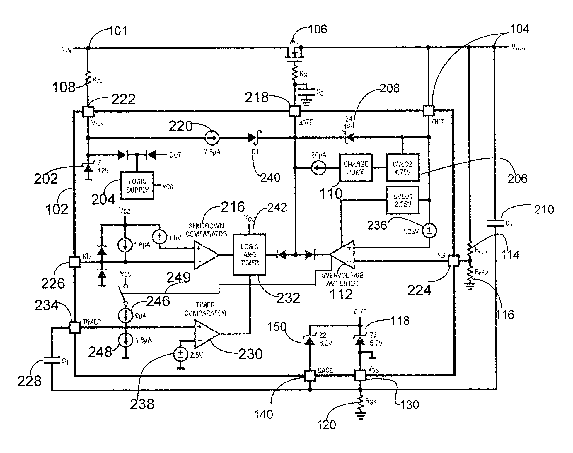
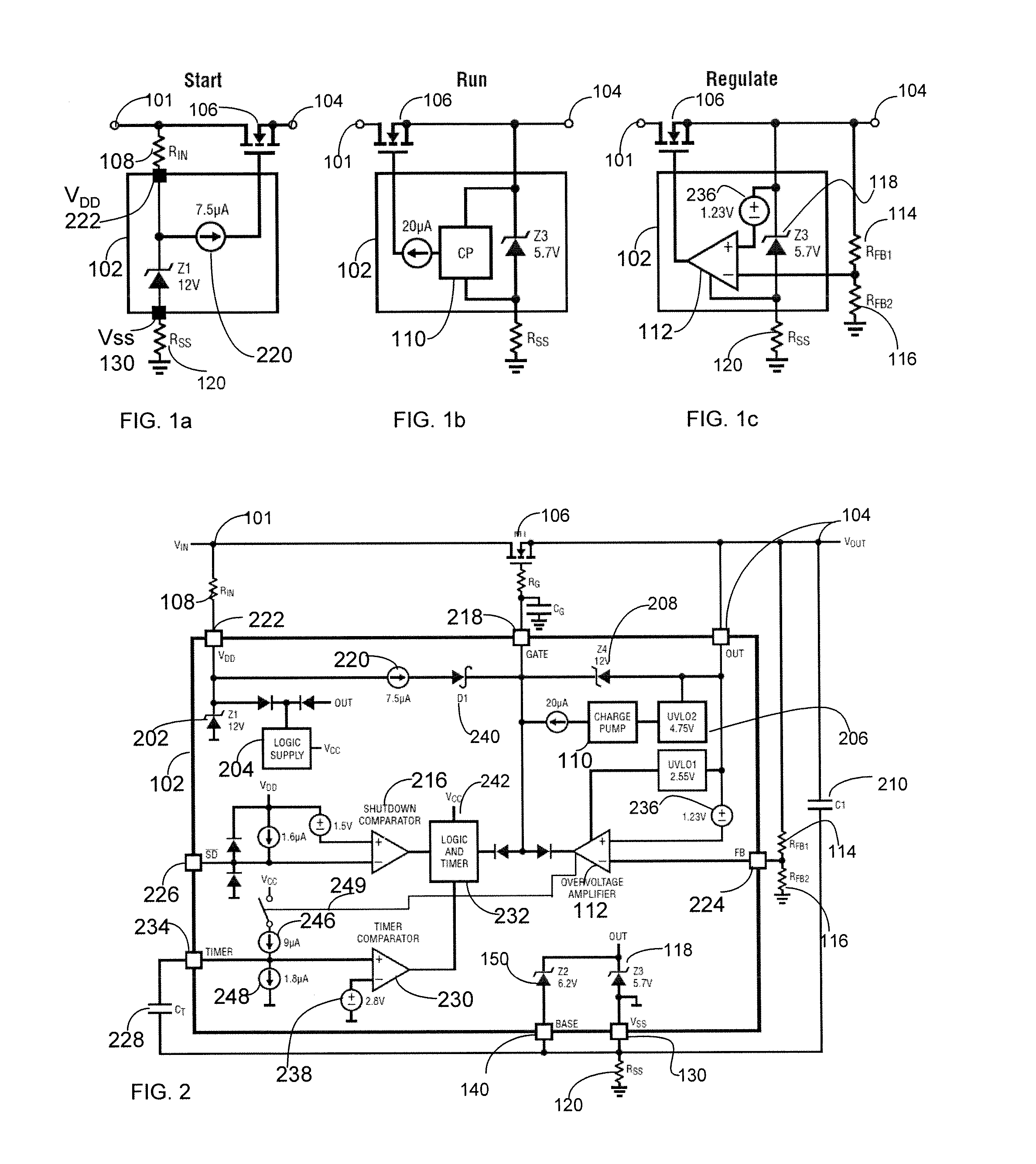
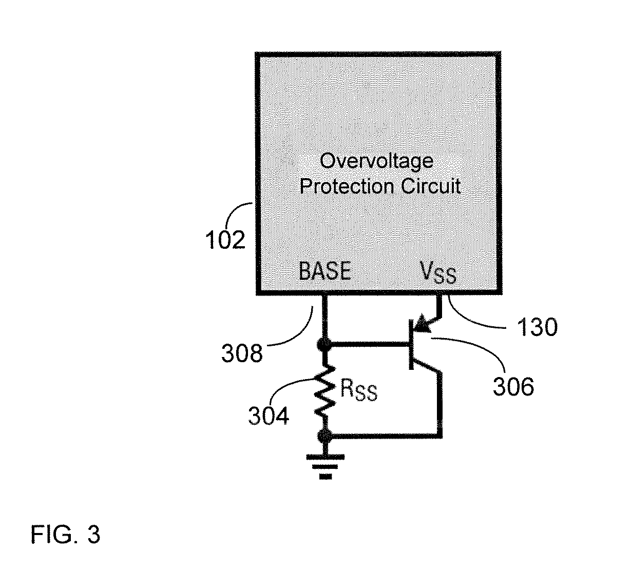
[0014]The various examples discussed below provide protection of overvoltage for electronic systems. The overvoltage protection circuitry can operate substantially independently of its voltage rating, thereby providing unlimited overvoltage protection on an electronic load. Put differently, the overvoltage protection circuit operates independently of external overvoltage. The overvoltage protection circuitry uses an adjustable floating topology to enable high voltage operation.

[0015]The overvoltage protection circuit distributes power to loads safe from overvoltage transients. Further, the overvoltage protection circuit includes two shunt ...


PUM


Abstract

An overvoltage protection method and circuit includes a positive supply input node, an output node, and a negative supply node. The overvoltage protection circuit further includes a first functional circuit configured to turn ON a MOSFET and maintain it in a low resistance state. A second functional circuit is configured to detect an overvoltage and control the gate of the MOSFET to regulate a voltage at the output node. A third functional circuit is configured to provide a startup wherein the overvoltage protection circuit is not damaged and/or to regulate an operating voltage such that an overvoltage does not appear on the overvoltage protection circuit. The external components include the MOSFET, which has a gate coupled to the output of the charge pump of the overvoltage protection circuit.

Description

TECHNICAL FIELD[0001]This disclosure generally relates to prevention of overvoltage of circuit systems and more particularly to circuit systems where the overvoltage protection circuit is isolated from the supply and ground.DESCRIPTION OF RELATED ART[0002]Electronic circuit systems can be vulnerable to damage by transient voltage spikes. If a voltage rises above a safe threshold, the circuit system protection circuitry attempts to limit the voltage supplied to an electronic circuit system by either blocking or by shorting to ground any unwanted voltage above a safe threshold.[0003]While circuitry that protects electronic circuit systems exists, protection at voltages higher than the breakdown of the overvoltage protection circuit may require a different approach. Typically, circuitry that controls the protection is limited in the amount of voltage it can protect against. Accordingly, there is a need for a control and protection circuit that can operate at a low voltage and is capabl...

Claims


Application Information

Patent Timeline
Patent Type & Authority Applications(United States)
IPC IPC(8): H02H9/04H02H3/06H02H3/20
CPCH02H1/06H02H9/048H02H9/04
Inventor DOBKIN, ROBERT CURTISSOO, DAVID HENRY
Owner ANALOG DEVICES INT UNLTD
Why Eureka
Try Eureka