
Power and bidirectional data transmission

a power and data transmission and data technology, applied in the field of power and data transmission systems and methods, can solve the problems of harmful leakage of electrical current into the body tissue, the mass of the battery and the associated integrated circuit, and the inability of other passive components to allow such a system to be directly attached to body parts,

Active Publication Date: 2012-11-15
ALFRED E MANN FOUND FOR SCI RES
View PDF2 Cites 26 Cited by
  • Summary
  • Abstract
  • Description
  • Claims
  • Application Information

AI Technical Summary

Benefits of technology

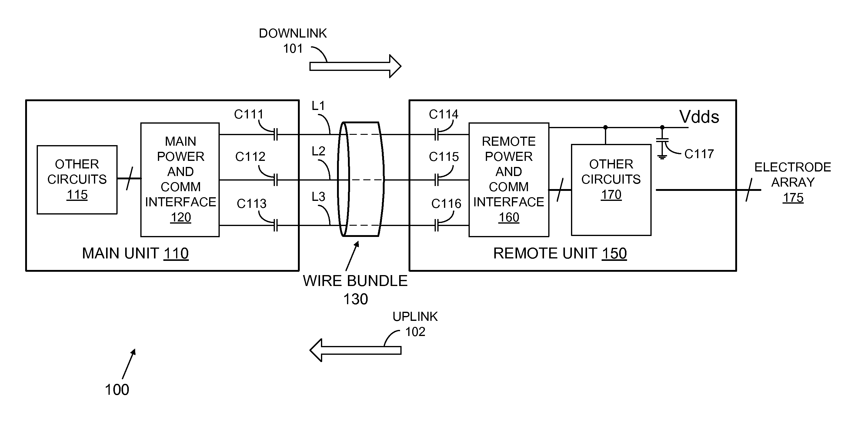
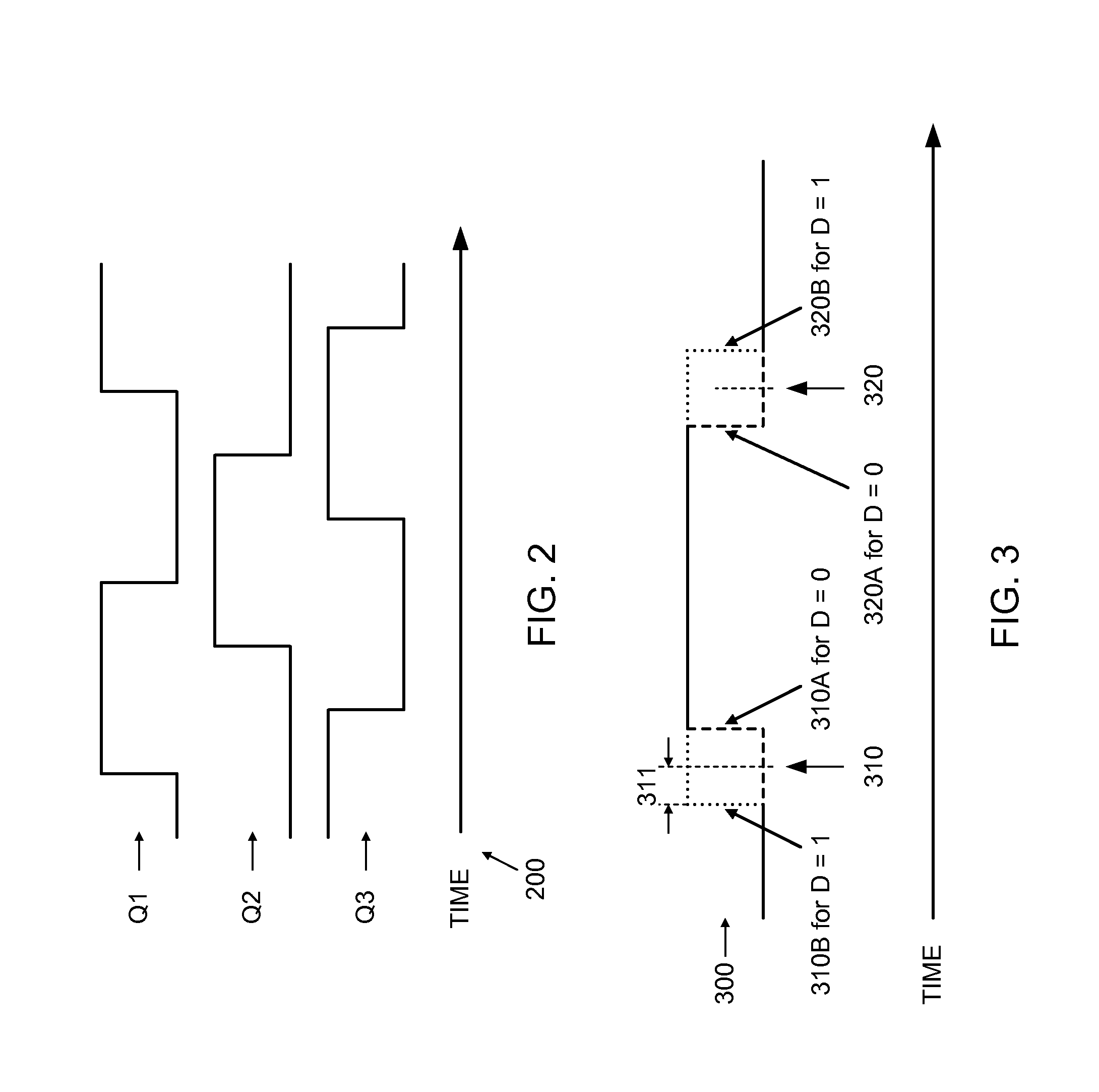
[0005]Systems and methods for power and bidirectional data transmission using a plurality of wires are described which are useful in body implanted electronics. A multiphase digital signal is sent from a main unit to a remote unit over the plurality of wires and is converted to a DC power signal used to power the remote unit. Uplink data is sent from the remote to the main over one selected wire during a predetermined time period for an uplink transmission by amplitude modulating the received digital signal at the remote. During an uplink,

Problems solved by technology

In an implantable battery powered biomedical device, the size and mass of the battery and the associated integrated circuits, as well as other passive components may not allow such a system to be directly attached to body parts, such as nerve bundles and cortices, directly.
When an implantable device is separated into a remote and main unit, problems can arise in transmitting power and data between the remote unit and the main unit.
An implanted system sending power between two or more devices implanted in body tissue cannot use DC to send power over wires from one device to another, because if there were a break in the insulation of one of the wires, then harmful leakage of electrical current into the body tissue could occur.

Method used


Image

  • Power and bidirectional data transmission
  • Power and bidirectional data transmission
  • Power and bidirectional data transmission

Examples


Embodiment Construction

[0017]Throughout the specification and claims, the following terms take at least the meanings explicitly associated herein, unless the context clearly dictates otherwise. The meanings identified below are not intended to limit the terms, but merely provide illustrative examples for use of the terms. The meaning of “a,”“an,” and “the” can include reference to both the singular and the plural. The meaning of “in” can include “in” and “on.” The term “connected” means a direct electrical, electro-magnetic, mechanical, logical, or other connection between the items connected, without any electrical, mechanical, logical or other intermediary there between. The term “coupled” means a direct connection between items, an indirect connection through one or more intermediaries, or communication between items in a manner that may not constitute a physical connection. The term “circuit” can mean a single component or a plurality of components, active and / or passive, discrete or integrated, that ...


PUM


Abstract

Systems and methods for power and bidirectional data transmission using a plurality of wires. A multiphase digital signal is downlinked from a main unit to a remote unit over the plurality of wires and is converted to a DC power signal used to power the remote unit. Uplink data is sent from the remote to the main over one selected wire during a predetermined time period for an uplink transmission by amplitude modulating the received digital signal at the remote. During an uplink, the output impedance of the line driver in the main unit connected to the wire selected for the uplink is increased to allow for the uplink amplitude modulation. The modulated signal is maintained within the noise margins of the digital circuits in the main and remote units.

Description

CROSS REFERENCE TO RELATED APPLICATIONS [0001]The present application claims the benefit from U.S. provisional application Ser. No. 61 / 383,690 filed on Sep. 16, 2010, which is incorporated herein by reference. The present application is a continuation in part of U.S. patent application Ser. No. 12 / 464,831 entitled Pulse Edge Modulation, filed on May 12, 2009, which is incorporated herein by reference. The present application is also a continuation in part of U.S. patent application Ser. No. 12 / 464,843 entitled Pulse Edge Demodulation, filed on May 12, 2009, which is incorporated herein by reference.FIELD OF THE INVENTION [0002]The present invention generally relates to systems and methods for power and bidirectional data transmission on a plurality of wires.BACKGROUND [0003]In an implantable battery powered biomedical device, the size and mass of the battery and the associated integrated circuits, as well as other passive components may not allow such a system to be directly attach...

Claims


Application Information

Patent Timeline
IPC IPC(8): H03K7/08
CPCH03K7/08H04B2203/547H04B2203/5466H04B3/548
Inventor LEE, EDWARD K. F.
Owner ALFRED E MANN FOUND FOR SCI RES
Learn More